
Note: Cylinder head reassembly is described in Section 1B.
Withdrawal
1. Disconnect the negative cable from the battery.
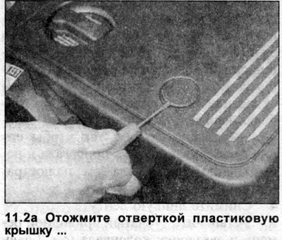
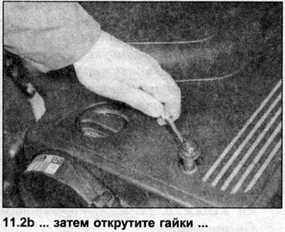
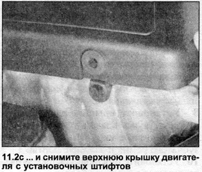
2. Remove the engine top cover and engine compartment bottom shield (see illustrations). If necessary, temporarily jack up the front of the vehicle.
3. Drain the engine oil.
4. Drain the liquid from the cooling system.
5. Loosen the brackets and disconnect all hoses from the cylinder head, noting their location.
6. Remove the auxiliary drive belt as described in Chapter 7.
7. Remove the timing belt tensioner and camshaft sprocket (see chapter 6). This procedure involves setting the engine to TDC.
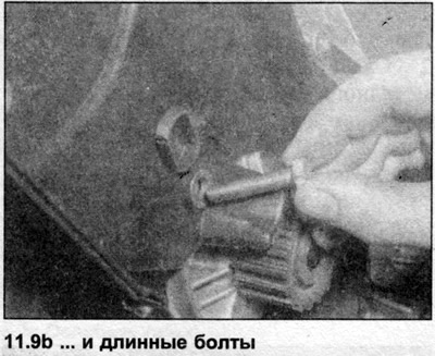
8. Turn off bolts of the bottom cover of a gear belt. Where necessary, first remove the thermoviscous fan assembly (see section 2).
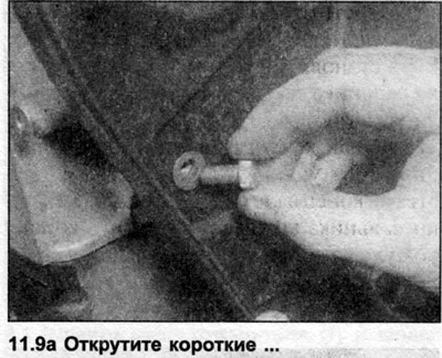
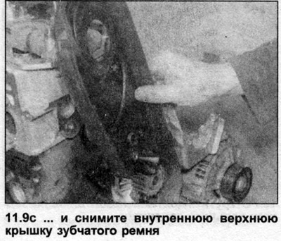
9. Turn off bolts and remove an internal top cover of a gear belt (see illustrations).
10. Remove the camshaft cover as described in Chapter 8.
11. Remove the fuel pump drive belt (see chapter 5).
12. Disconnect and remove the injector fuel feed lines as described in Section FOR. Disconnect the outlet hoses from the injectors.
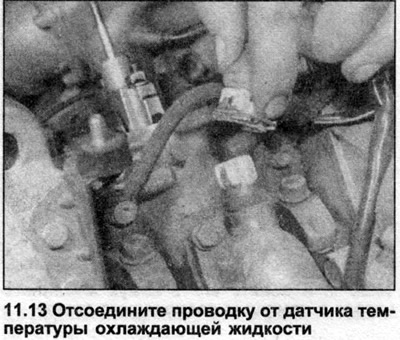
13. Disconnect all fuel and cooling system wiring, labeling each connector to simplify subsequent installation (see illustration). Disconnect the supply wires from the glow plugs.
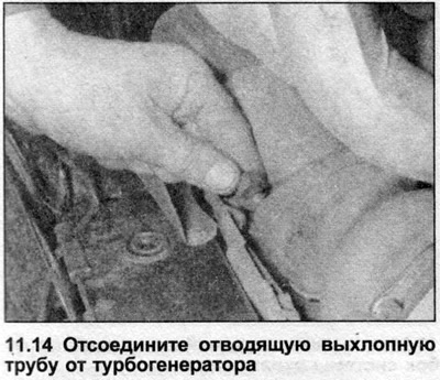
14. On DE, NC and 1T engines, remove the turbogenerator as described in Section 3B. Where access to the turbogenerator is limited, remove it together with the exhaust manifold. In this case, it is necessary to unscrew the nuts and disconnect the exhaust pipe from the turbogenerator (see illustration).
15. On 3D engines, disconnect the outlet pipe from the exhaust manifold (Section 3B). Support the outlet pipe with an axle support and remove the gasket.
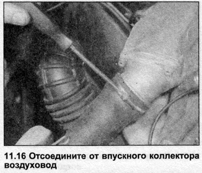
16. See Sections 3A And 3B and remove the intake and exhaust manifolds (see illustration).
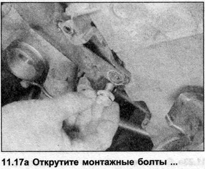
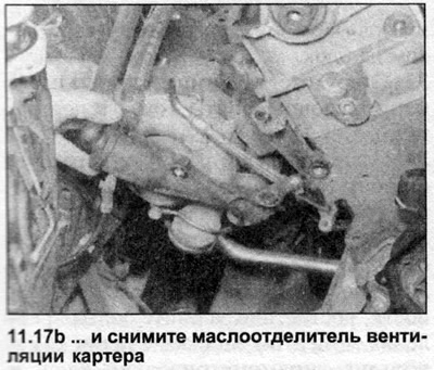
17. Remove the bolts and remove the crankcase ventilation oil separator on the right side of the engine (see illustrations).
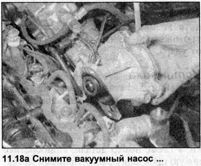
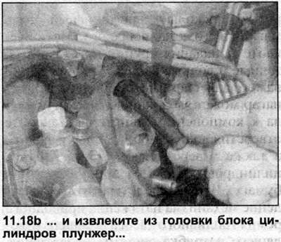
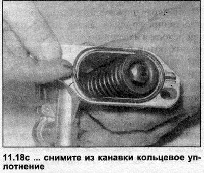
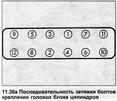
18. Remove the vacuum pump and plunger from the left side of the cylinder head (see Section 9). The plunger must be removed to gain access to one of the cylinder head bolts. Remove the O-ring from the groove in the vacuum pump housing (see illustrations).
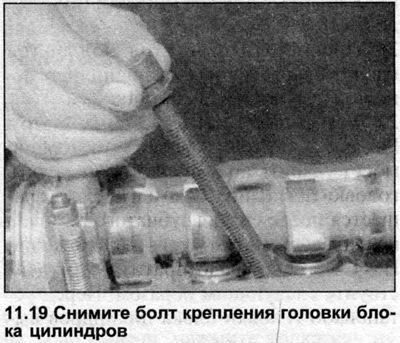
19. In the reverse order shown in illustration 11.36a, gradually loosen the cylinder head mounting bolts (half a turn per reception), unscrew them by hand and remove them together with the washers. Discard the bolts - they must be replaced (see illustration).
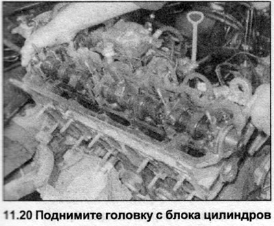
20. Make sure nothing else is connected to the cylinder head, then lift the head off the block (see illustration). It is recommended to do this together, because. the head is heavy.
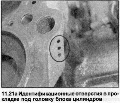
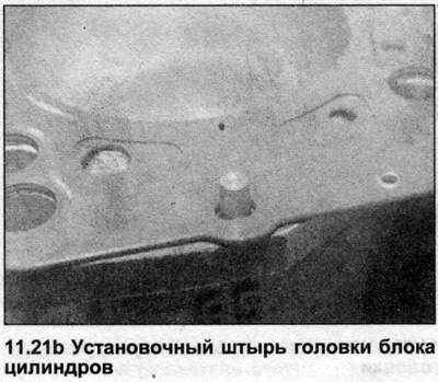
21. Remove the gasket from the top of the block, paying attention to the identification holes located on its right edge. If the alignment pins are loose, remove them and store with the head to prevent loss (see illustrations). Don't throw away the shim until you need it as a sample.
22. If the cylinder head needs to be disassembled, refer to Section 1B.
Inspection
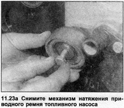
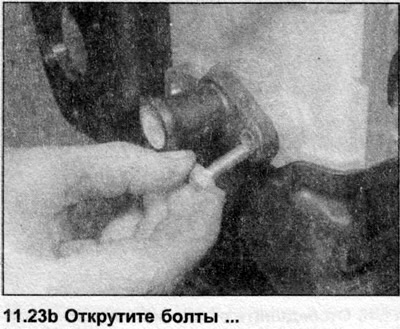
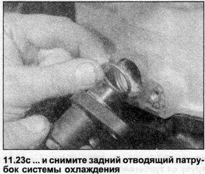
23. Clean the mating surfaces of the head and cylinder block/crankcase. Using a plastic or wooden scraper, remove the traces of the gasket and soot; also clean the piston heads. Work very carefully as aluminum alloy is soft and easily damaged. Keep carbon deposits out of the oil and water passages - this is especially important for the lubrication system, as carbon deposits can block the oil supply to engine components. Seal the water and oil passages and the bolt holes in the cylinder block using masking tape and paper. To prevent damage to the fuel pump drive belt tensioner and rear coolant outlet pipe, temporarily remove them from the rear of the cylinder head (see illustrations).
24. Check up contact surfaces of the block of cylinders and a head on presence of roughnesses, deep scratches and other damages. Small indentations can be carefully removed with emery cloth. Please note that regrinding of the head is not possible - see Section 1B.
25. Check the seating surface of the cylinder head for deformation using the edge of the ruler (see Section 1B).
26. Clean the holes for the cylinder head bolts using a suitable tap.
27. The design of all the engines described in this Section is such that the pistons can hit the valves and damage the heads of the latter if the camshaft rotates after removing the toothed belt, while the crankshaft is in the TDC position. To prevent this, proceed as follows. Before installing the cylinder head, bring the number 1 piston to TDC, then turn the crankshaft a few degrees against its stroke to deflect the pistons from impact.
Installation
28. Locate the manufacturer's identification marks on the old cylinder head gasket. They can be either perforated holes or notches located on the edge of the gasket, as well as a part number. Get a new gasket with identical marks (unless new pistons have been installed).
29. If new pistons were installed during engine overhaul, refer to Section 1B and measure piston protrusion height before purchasing a new cylinder head gasket. Select a new gasket according to the measurement result (see Section 1B Specifications).
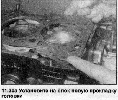
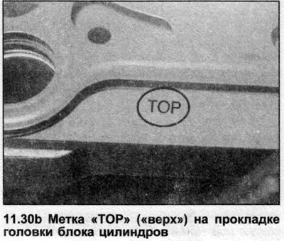
30. Place a new gasket on the cylinder block by pushing it onto the dowel pins. Make sure the gasket is facing up with the manufacturer's mark «TOR» («top») and part number.
31. Cut off the heads of the two old cylinder head bolts, cut grooves in their upper ends (a screwdriver will then be inserted into them to unscrew and remove the bolts) and screw them into opposite ends of the cylinder block so that the head sits exactly on the cylinder block when installed.
32. With the help of an assistant, place the head on the cylinder block, observing the position of the alignment pins. Make sure the gasket has not moved before lowering the head with all your weight onto the block.
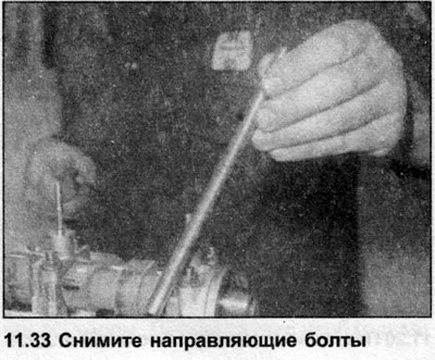
33. Unscrew and remove homemade guide bolts (see illustration).
34. Lightly lubricate the threads and the reverse side of the heads of the new cylinder head bolts with oil.
35. Carefully insert each bolt into the hole and tighten them by hand.
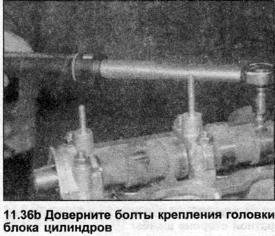
36. Working in the sequence shown, progressively tighten the mounting bolts to Stage 1 torque using a torque wrench and suitable socket (see illustration). In the same sequence, tighten them with Stage 2 torque.
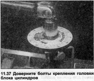
37. All in the same sequence, tighten the bolts to the angle specified in the Specifications (Stage 3), using the socket and extension rod. An angle gauge is recommended to ensure accuracy. If a template is not available, paint the alignment marks on the bolts and head, tighten the bolts and check the angle using the marks.
Note: The Specifications provides information on retightening the bolts after the engine has warmed up to normal operating temperature.
38. Install the vacuum pump as described in Section 9.
39. Install intake and exhaust manifolds (Sections BEHIND And 3B).
40. On DE, NC and 1T engines, where removed, install the turbogenerator as described in Section 3B.
41. On 3D engines, attach the exhaust pipe to the exhaust manifold by installing a new gasket (Section 3B).
42. Connect all electrical wiring disconnected before removal.
43. Connect the fuel outlet and supply lines to the injectors as described in Section FOR.
44. Install the fuel pump drive belt (see chapter 5).
45. Install the camshaft cover (see chapter 8).
46. Establish an internal top cover of a gear belt and tighten bolts. Please note that the threads of the bolt installed below the camshaft must first be coated with a blocking compound.
47. Establish the bottom cover of a gear belt and tighten bolts. Where necessary, install a thermoviscous fan assembly.
48. Bring the engine to the TDC position and install the toothed belt tensioner, camshaft sprocket and the toothed belt itself (see chapter 6).
49. Install auxiliary drive belt (see chapter 7).
50. Connect the cooling system hoses to the cylinder head and tighten the clamps.
51. Fill the cooling system.
52. Fill the engine with the required amount of clean, specified grade oil.
53. Install the bottom guard and lower the vehicle to the ground.
54. Connect the negative cable to the battery.
55. Start the engine and warm it up to normal operating temperature.
56. Turn off the engine and remove the camshaft cover as described in Chapter 8.
57. Working in the sequence shown, tighten the cylinder head bolts to the specified angle (Stage 5).
Note: On models with 1T, CN, NC and DE engines, the cylinder head bolts must be tightened 90°after the vehicle has traveled 1000 km.
58. Install the camshaft cover (see chapter 8).
Visitor comments