
Note: Both new and remanufactured cylinder heads are available from Audi dealers. Special tools are required to disassemble and inspect the head, and the necessary components are not always available for sale. Therefore, it is probably more practical to buy a remanufactured head than to reassemble it yourself.
Disassembly
1. Remove the head from the cylinder block as described in Section 1A.
2. Remove the injectors and glow plugs (see sections 3A and 4B).
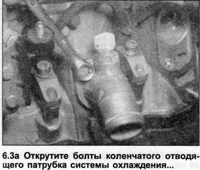
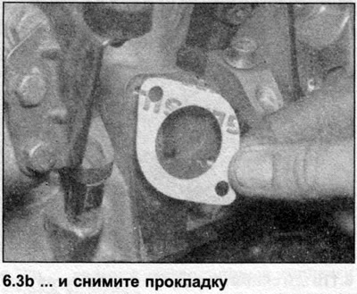
3. Where available, see. Section 2 and remove the elbow outlet pipe of the cooling system together with the gasket/O-ring (see illustrations).
4. Where available, unscrew the coolant sensor and oil pressure sensor from the cylinder head.
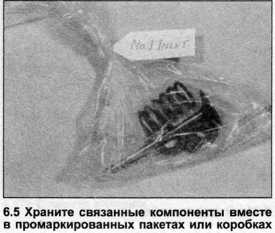
5. Store related components together in labeled containers after removal to avoid confusion during installation and to ensure that each group of parts is installed exactly in the same place (see illustration). Installing components haphazardly will cause them to wear out faster. Note that cylinder #1 is located at the front end of the engine.
6. Make sure the camshaft bearing caps have manufacturer identification marks. If not, mark them yourself using a marking tool or punch.
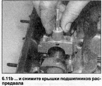
7. Remove the camshaft bearing caps as described below.
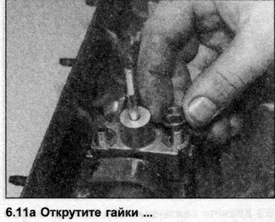
8. Loosen the nuts of bearing caps No.2 and No.4, then bearing caps No.1 and No.3 (see illustration). Working in a diagonal sequence, turning the nuts one-half turn at a time, remove the nuts, then remove the bearing caps. Store the caps in the order they were removed and mark the correct orientation of each.
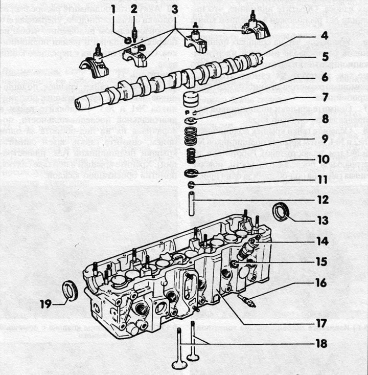
6.8 Cylinder Head Components
1 - Nut
2 - Pin
3 - Bearing caps
4 — Camshaft
5 - Hydraulic pusher
6 — Valve crackers
7 — Upper valve spring support
8 — Outer valve spring
9 — Inner valve spring
11 — Valve stem oil seal
12 — Valve guide bushing
13 — Rear oil seal
14 — Nozzle
15 — Thermal insulation shield
16 - Glow plug
17 — Cylinder head
18 — Valves
19 — Front oil seal
Note: The camshaft bearing caps are numbered 1 through 4 from the toothed belt end.
9. Remove the seal from the front end of the camshaft - it must be replaced. On the 3D engine, also remove the rear camshaft seal.
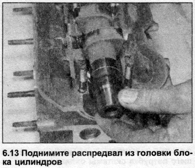
10. Carefully lift the camshaft out of the cylinder head, keeping it horizontal to avoid damaging the cams and bearing journals. Remove the seal from the front end of the shaft.
Engine 1T
11. Remove the nuts from bearing caps #2 and #4, then bearing caps #1 and #3. Loosen the nuts in a diagonal sequence, turning them half a turn at a time, remove the nuts, then remove the bearing caps (see illustrations). Store lids in the order they were removed, labeling the orientation of each.
Note: The camshaft bearing caps are numbered 1 through 4, starting from the timing belt end.
12. Remove the front and rear camshaft seals and discard them - they must be replaced.
13. Carefully lift the camshaft from the cylinder head, keeping it horizontal to avoid damaging the cams and bearing journals (see illustration).
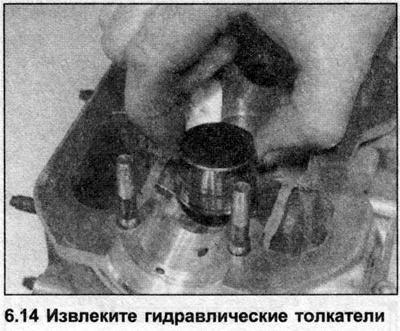
14. Remove the hydraulic lifters from the guides and store them with the valve contact surface facing down to prevent oil spillage (see illustration). Mark each valve lifter as they must be installed on the same valves when reassembled. Random installation will greatly accelerate wear.
All engines
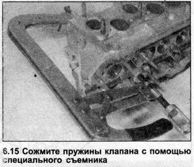
15. Turn the cylinder head on its side. Using a special puller, alternately compress each of the valve springs and remove the crackers. If the spring support is jammed, tap the upper paw of the puller with a hammer (see illustration).
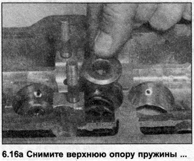
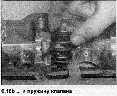
16. Remove the puller and remove the upper spring support, the valve spring itself and its lower support (see illustrations).
Note: Depending on the engine, the valves may have concentric twin springs or single springs.
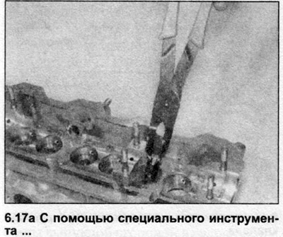
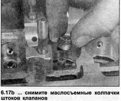
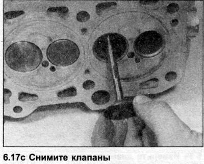
17. Using pliers or a special tool, remove the valve stem oil seal. Remove the valve from the cylinder head gasket side. Repeat this step on the remaining valves (see illustrations).
Cleaning
18. Using a suitable solvent, remove oily residue from the cylinder head, paying particular attention to the camshaft bearings, hydraulic lifter bores, valve guides, and oil grooves. Scrape all traces of old gasket from the mating surfaces, being careful not to damage the soft metal. Turn the head over and, using a blunt instrument, scrape carbon deposits from the combustion chambers and bore edges. Finally, wash the head with solvent to remove any remaining dirt.
19. Clean the valve heads and stems using a soft wire brush. If the carbon layer is too thick, first scrape off the bulk of it with a blunt tool, then use a wire brush.
20. Clean the remaining components thoroughly using solvent and allow them to dry. Discard the seals - they are subject to replacement.
Inspection
Cylinder head
Note: On diesel engines, the cylinder head and its components cannot be rebuilt (although the valves can be ground in). If the head is damaged or worn beyond the specification limits, replace it.
21. Carefully inspect the head for damage. Pay particular attention to the areas adjacent to the valve seats and spark plugs. If cracks found in this area are no wider than 0.5 mm, manufacturers claim that the cylinder head does not need to be replaced. Otherwise, the head must be replaced.
22. Valve seats that are not too deeply burned can be restored by lapping the valves to them as described later in this Section. Badly worn or damaged seats can be reground, but this work should be left to a specialist.
23. Check the cylinder head for deformation using the edge of a ruler and a set of feeler gauges. Take measurements on the contact surfaces with the intake and exhaust manifolds (longitudinal). Take several measurements across the seating surface of the head (see illustration). Compare the measurement results with the data given in the Specifications. On petrol engines, the head can be reground.
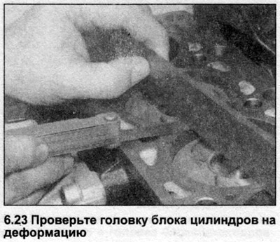
24. Measure the height of the cylinder head (from the head seating surface to the valve cover gasket surface). Minimum height is specified in the Specifications (where specified by the manufacturer).
Camshaft
25. Inspect the camshaft lobes and journals for signs of wear. Their surfaces should be smooth and have a dull shine. Scratches, pitting, and polished areas indicate wear that will occur even faster now that the outer reinforced layer has been destroyed. Be sure to replace worn components.
Note: If signs of wear are found on the working surface of the cams, also inspect the corresponding tappets, they are probably also worn.
26. Where fitted, inspect the distributor drive gear for damage and signs of wear. Excessive chain slack caused by worn gear teeth will throw off the ignition timing.
27. If the machined surfaces of the camshaft have changed colour slightly or even turned blue, the shaft has probably been overheated, possibly due to insufficient or poor quality lubrication. Overheating may have caused the shaft to warp. To check this, place the camshaft between two V-bearings and use a micrometer to measure the runout of its centre journal. If it exceeds the value given in the Specifications, replace the camshaft.
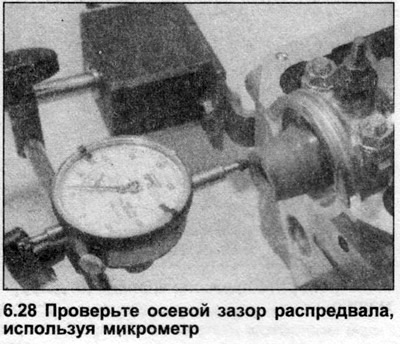
28. To measure the camshaft end play, temporarily install the shaft into the cylinder head, then the outer bearing caps and tighten the mounting nuts to Stage 1 tightening torque (see Specifications). Attach a micrometer to the end of the cylinder head facing the timing belt and align the probe with the camshaft axis. Move the camshaft along the axis until it stops in one direction, then rest the probe against the end of the shaft and zero the device. Move the camshaft as far as possible in the opposite direction and record the readings. Check the result by moving the shaft to its original position (see illustration).
Note: The hydraulic lifters must be removed when performing this measurement.
29. Compare the result obtained with the data given in the Specifications. Excessive axial clearance is unlikely to be caused by wear of only one of the components, so most likely it will be necessary to replace the camshaft, cylinder head and bearing caps.
30. Measure the camshaft bearing operating clearance. One method (you will need micrometers or internal/external calipers) consists of measuring the diameter of the camshaft bearing journals and the diameter of the holes formed by the bearing caps and the cylinder head. The difference between these two measurements is the bearing operating clearance.
31. Second (and more accurate) the method consists of using a special tool called Plastigage. The tool consists of a scale and plastic threads of round cross-section. Proceed as follows.
32. Make sure that the bearing surfaces in the cylinder head, on the camshaft and the caps are completely clean and dry. Place the camshaft in the cylinder head.
33. Place a piece of Plastigage on each of the camshaft bearing journals.
34. Install the bearing caps and gradually tighten the retaining nuts to the torque specified in the Specifications. This will flatten the Plastigage thread.
Note: Where tightening is done in several stages, tighten the nuts only to the first stage. Do not rotate the camshaft until the bearing caps are removed - this will distort the measurement results.
35. Loosen the nuts and carefully remove the bearing caps so as not to press on the Plastigage thread, which should remain on the camshaft.
36. Apply the scale supplied with the tool to the journal of each bearing and compare the width of the flattened threads with it. The value of the bearing working clearance is indicated on the scale.
37. Compare the measurement results with the data given in the Specifications; if the working clearance of at least one of the bearings is outside the permissible tolerances, the camshaft and cylinder head should be replaced.
38. Finally, remove the camshaft and wash all traces of Plastigage from it and the bearing caps.
Note: On all engines described, the valve heads cannot be reground, although they can be ground.
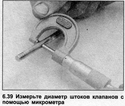
39. Inspect each valve for signs of wear. Check the valve stems for wear and scratches. Measure their diameter at several points with a micrometer to ensure that it is the same along the entire length of the stem (see illustration).
40. Valve heads should not be cracked, heavily corroded or burnt. Note that light pitting can be removed by grinding the valve.
41. Check that the end surface of the valve stem is not corroded or worn, which would indicate a faulty hydraulic tappet or incorrect valve clearance adjustment.
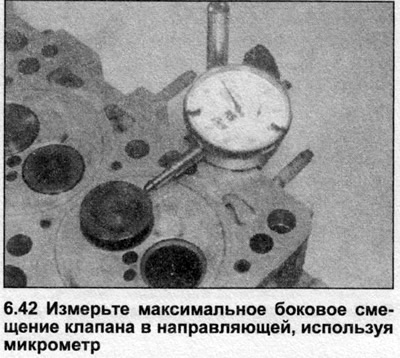
42. Insert each valve into its corresponding guide in the cylinder head (the end of the valve stem should be flush with the top of the guide) and rest the micrometer probe against the edge of the valve head. Move the valve horizontally and measure the maximum lateral displacement of the stem in the guide (see illustration).
43. If the measurement result exceeds the data given in the Specifications, the valve and its guide bushing should be replaced.
Note: The valve guides are pressed into the cylinder head and require a hydraulic press to remove them.
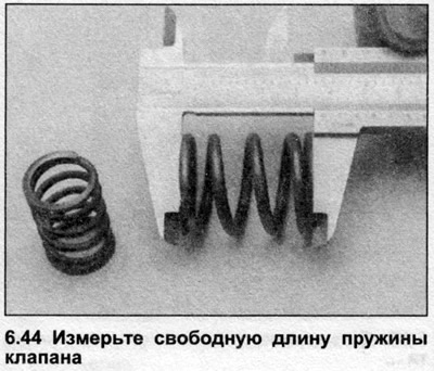
44. Using a caliper, measure the free length of each valve spring. Manufacturers do not provide any data, and the only way to determine whether a spring is weak is to compare its free length to the length of a new component (see illustration).
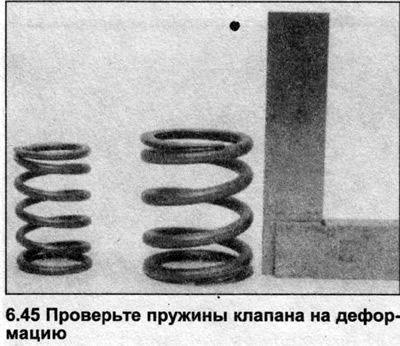
45. Place each spring on a flat surface and check them for deformation using a square (see illustration). If any of the springs are damaged, deformed or weakened (its free length is less than the free length of the new spring), replace it.
Assembly
46. To achieve a tight seal between the valves and the seats, they need to be ground in. This will require coarse and fine-grained grinding paste and a special tool - a mechanical (rubber suction cup) or with electric drive.
47. Apply a small amount of fine-grained grinding paste to the valve seat contact surface of the valve head. Turn the cylinder head upside down with the combustion chambers facing upward and insert the valve into its corresponding guide. Attach the grinding tool to the valve head and, rotating the valve back and forth half a turn, grind its head, grinding it against the seat. Lift the valve periodically to redistribute the paste (see illustration).
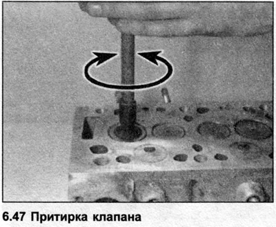
48. Continue lapping until the valve/seat contact surfaces are dull grey. Repeat the procedure on the remaining valves.
49. If the valves and their seats are badly pitted, first use a coarse grinding paste. Note that the Specifications give a maximum length of the valve stem protruding from the guide bushing. If this part of the stem is excessively extended due to grinding (the valve seat became deeper), hydraulic lifters will not function properly.
50. Proceed as described above, continuing to grind until the contact surfaces acquire an even, dull color. Wash off the coarse paste with solvent and repeat the procedure using a fine-grained compound.
51. Once all the valves have been lapped, remove all traces of grinding compound from the cylinder head and valves using solvent and allow to dry.
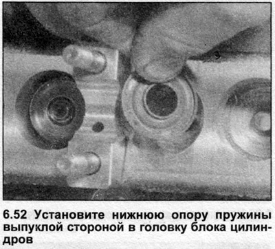
52. Turn the head over onto its side wall. Install the lower spring support with the convex side into the cylinder head (see illustration).
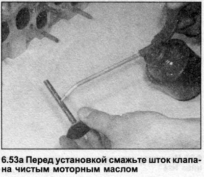
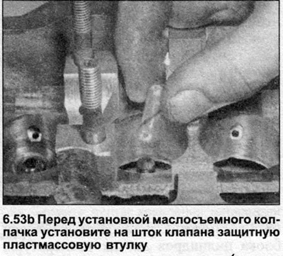
53. Lubricate the valve stem with clean engine oil and insert it into the guide. Install one of the protective plastic bushings sold with new valve stem seals onto the end of the stem - it will protect the seal from damage during installation (see illustrations). Repeat the action on the remaining valves.
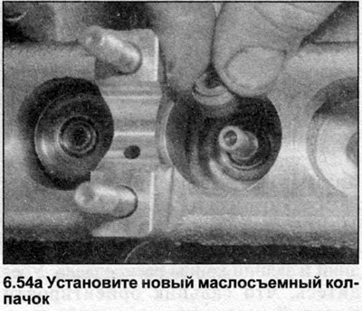
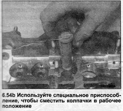
54. Dip the new valve stem seal in clean engine oil and carefully slide it over the valve into the guide bushing. Use a suitable socket or special tool to drive the seal into position (see illustrations). Remove the protective sleeve.
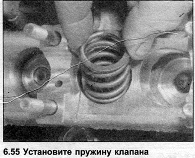
55. Install the valve springs (see illustration). Make sure the springs are seated correctly on the lower supports.
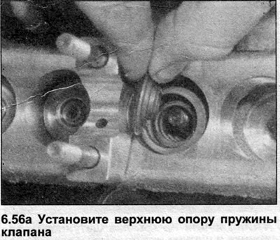
56. Install the upper spring seats, then using a spring puller, compress the springs so that the upper seat moves below the valve stem keeper grooves. Install the valve keepers, using a drop of grease to hold them in the grooves (see illustrations). Gradually release the pressure of the spring compressor, making sure that the crackers do not shift.
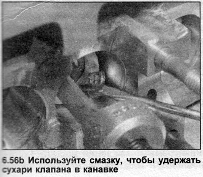
57. Repeat this step on the remaining valves. To adjust the position of the components after installation, tap the end of each valve stem with a mallet, covering the stem with a wooden block to protect it from damage. Again, make sure that the valve cotters are locked by the upper spring seat.
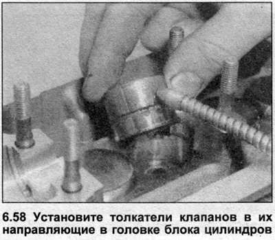
58. Lubricate the side surfaces of the hydraulic tappets with clean engine oil and install the tappets in their working position in the cylinder head. Push them down so that they touch the valves, then lubricate the contact surfaces of the camshaft lobes (see illustration).
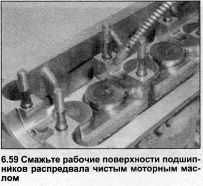
59. Lubricate the bearing surfaces on the camshaft and in the cylinder head with clean engine oil (see illustration).
60. Carefully lower the camshaft into the cylinder head, making sure that the cam lobe running surfaces for cylinder No. are facing upwards. Support the ends of the shaft to avoid damaging the cam lobe and journals.
61. Dip new oil seals in engine oil, then install them onto the front and rear ends of the camshaft. Make sure the seal faces outward and do not damage the seal lip.
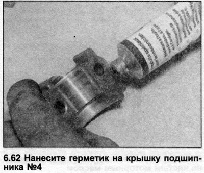
62. Lubricate the contact surfaces of bearing cap No.4 with sealant (see illustration).
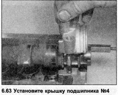
63. Lubricate the upper surfaces of the camshaft bearing journals with oil, then install bearing caps No.2 and No.4 (see illustration). Make sure the caps are oriented correctly and each one is in the same position, then gradually tighten the mounting bolts to the torque specified in the Specifications. To avoid camshaft tilt, install bearing cap #2 first, then press on the camshaft and install bearing cap #4.
64. Lubricate the contact surfaces of bearing cap No.1 with sealant, then install caps No.1 and No.3 and gradually tighten the nuts to the tightening torque specified in the Specifications.
65. Where available, install the coolant temperature sensor and oil pressure sensor in the cylinder head.
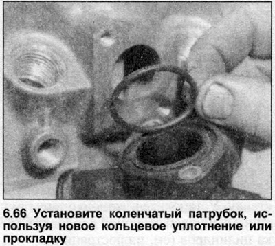
66. Where necessary, install the coolant outlet elbow with a new gasket/O-ring as described in Section 2 (see illustration).
67. Install the injectors and glow plugs (see sections 3A and 4B).
68. Install the cylinder head (see Section 1A).