Repair Chevrolet Repair Toyota Repair Honda Repair AvtoVAZ Repair Mercedes-Benz Repair BMW Repair Opel
Home  |  Contacts  |  Sitemap  |    
English Русский
Български
Беларускі
Український
Српски
Hrvatski
Română
Polski
Slovenský
Magyar
AudiManual.ru


  • AUDI 80
  • AUDI 100
  • AUDI A3
  • AUDI A4
  • AUDI A6
  • AUDI A8
  • AUDI Q
  • OTHER
  • ARTICLES
C4 (1990-1994) C4 (1990-1994, petrol) C3 (1982-1990) C3 (1982-1990, petrol) C3 (1982-1990, diesel)

Main and connecting rod bearings — inspection and selection of liners (Audi 100 C3)

  • Home
  • Audi 100
  • C3 (1982-1990, diesel)
  • Power unit
  • Engine removed
  • Main and connecting rod bearings — inspection and selection of liners
            0
Table of contents: Inspection ↓ Selection of main and connecting rod… ↓

Inspection


1. Although the main and connecting rod bearing shells should be replaced during an engine overhaul, save the old shells for detailed inspection as they can provide valuable information regarding the condition of the engine (see illustration).

1. Although the main and connecting rod bearing shells should be replaced during an engine…


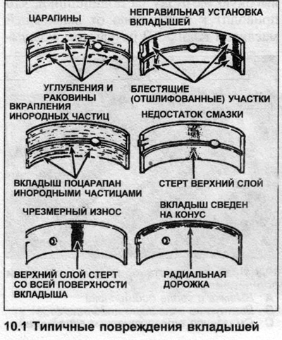
2. Bearing damage may be caused by insufficient lubrication, foreign particles, engine overload, or corrosion. Regardless of the cause, it must be corrected before reassembling the engine.

3. Remove all main and connecting rod bearing shells and lay them out on a clean work surface in the same order as they were installed in the engine. This will allow you to associate the bearing damage with the corresponding crankshaft journal. Do not touch the inner surface of the bearings, you can damage it.

4. Foreign particles enter the engine in various ways. They can be left in the engine during assembly or penetrate through filters or the crankcase ventilation system. Often, metal grains are found that are left over from regrinding or formed during normal engine wear. Foreign particles that enter the bearings are embedded in the soft working layer of the liners, where they are easy to detect. Large particles do not sink into the material of the liners, but scratch the liners and journals. The best way to prevent bearing failure due to this cause is to thoroughly clean all components and maintain impeccable cleanliness during engine assembly. In addition, frequent and regular changes of engine oil and filter are recommended.


5. Lack of lubrication has many interrelated causes. These may include: overheating (makes the oil less viscous, which causes its layer on the bearings to become thinner), overload (squeezes oil from the bearing surface) or leaks (bearing clearances are excessive, oil pump is worn out or engine speed is high). Blockage of the lubrication passages, which is usually the result of misalignment of the bearing lubrication holes, also leads to a lack of lubrication and causes bearing failure. When a bearing fails due to lack of lubrication, the bearing layer will be worn away or peel off from its steel backing. Temperatures can rise to the point where the steel backing turns blue from overheating.

6. Driving style also affects bearing life. Full throttle and long-term operation at low speeds (engine overload) put a very high load on the bearings, which causes the oil film to be pushed away from the liners. As a result, the liners bend and a network of small cracks forms on them (a "fatigue" failure). Ultimately, the working layer of the bearing liner will disintegrate into pieces and break away from the steel base.

7. Short trips cause bearing corrosion because the engine does not heat up enough to repel compressed water vapor and corrosive gases. The vapors are adsorbed by the engine oil, forming acid and sludge. When this oil gets into the engine bearings, the working layer of their bearings oxidizes.

8. Incorrect selection of the bearing shell will also cause bearing failure. Too large shells that fit tightly into the bearing leave insufficient working clearance, which leads to a lack of lubrication.


9. When assembling, do not touch the working surface of the inserts with your fingers - this may scratch it.

10. As mentioned at the beginning of this Chapter, the liners should be changed after each removal.

Selection of main and connecting rod bearings


11. We sell main and connecting rod bearing shells of both nominal and repair sizes (see Specifications).

12. After installing new liners, check the operating clearances of the crankshaft bearings (see Chapter 12).
The article was checked by auto expert Nikita Rudakov
This article is available at russian, bulgarian, belarusian, ukrainian, serbian, croatian, romanian, polish, slovak, hungarian

Share information:
Previous articles
Audi 100 C3: Engine removed
Next articles

Cylinder block/crankcase — cleaning and inspection
Crankshaft — removal and inspection
Piston/Connecting Rod Assemblies — Removal and Inspection
Cylinder head — disassembly, cleaning, inspection and assembly
Engine assembly sequence
Crankshaft — installation and checking of working clearance
Pistons and piston rings — assembly
Piston/Connecting Rod Assemblies — Installing and Checking…


Similar articles on other Audi car models:
Crankshaft and main bearings — check Audi 80 B3 (1986-1991, petrol)
Visual inspection of the gearbox for leaks Audi A3 Type 8L (1996-2003)
Crankshaft bearings — inspection and selection Audi A4 B5 (1994-2001)
Main and connecting rod bearings Audi A6 C4 (1994-1997)
Visual inspection of gearbox tightness Audi A8 D2 (1994-2002)
Pistons and connecting rods Audi Q5 Type 8R (2008-2017)
Removal and installation the toothed belt for the main drive Audi A2 (1999-2005)
Link to this page in different formats


Visitor comments

No comments yet


How much will 48 + 30 =


100(C4, 1990-1994) 
  • General information
  • User manual
  • Power unit
  • Engine repair
  • Ignition system
  • Fuel system (gasoline)
  • Fuel system (diesel)
  • Lubrication system
  • Cooling system
  • Exhaust system
  • Transmission
  • Clutch
  • Car gearbox
  • Drive shafts
  • Chassis
  • Car suspension
  • Steering
  • Wheels and tires
  • Brake system
  • Body
  • Ventilation and heating
  • Body repair
  • Electrical equipment
  • Power devices
  • Lighting and appliances
  • Electrical circuits
 
100(C4, 1990-1994, petrol) 
  • General information
  • Operation and maintenance
  • Power unit
  • Engine repair
  • Exhaust system
  • Cooling system
  • Supply system
  • Air filter
  • Mono-Motronic injection system
  • Digifant injection system
  • KE-III-Jetronic and KE-Motronic
  • MPI and MPFI injection system
  • Transmission
  • Clutch
  • Car gearbox
  • Chassis
  • Suspension and steering
  • Brake system
  • Wheels and tires
  • Body
  • Exterior
  • Interior
  • Electrical equipment
  • Fuses and relays
  • Power devices
  • Ignition system
  • Lighting and signaling
  • Equipment and devices
  • Electrical circuits
 
100(C3, 1982-1990) 
  • General information
  • User manual
  • Maintenance
  • Specifications
  • Power unit
  • Engines 4-cylinder
  • Engines 5-cylinder
  • Diesel engine
  • Cooling system
  • Power system (carburetor)
  • Power system (injector)
  • Fuel system (diesel)
  • Transistor ignition system
  • Electronic ignition system
  • Transmission
  • Clutch
  • 4 speed gearbox 014
  • 5 speed gearbox 013 and 093
  • 5 speed gearbox 016 and 012
  • Shift mechanism KP 016
  • Automatic transmission
  • Front wheel drive
  • Chassis
  • Front suspension
  • Rear suspension
  • Steering
  • Brake system
  • Body
  • Body elements
  • Electrical equipment
  • Lighting and appliances
  • Power devices
  • Electrical circuits
 
100(C3, 1982-1990, petrol) 
  • General information
  • Maintenance and operation
  • 4 cylinder engine
  • Engine repair
  • Cooling and lubrication system
  • Supply system
  • Ignition system
  • 5 cylinder engine
  • Engine repair
  • Cooling and lubrication system
  • Supply system
  • Ignition system
  • Transmission
  • Clutch and drive shafts
  • 4 speed gearbox 014
  • 5 speed gearbox 013 and 093
  • 5 speed gearbox 016 and 012
  • Automatic gearbox
  • Chassis
  • Steering
  • Front suspension
  • Rear suspension
  • Brake system
  • Body
  • Body elements
  • Doors, locks and windows
  • Body repair
  • Electrical equipment
  • Equipment and devices
  • Power devices
  • Electrical circuits
 
100(C3, 1982-1990, diesel) 
  • General information
  • User manual
  • Maintenance
  • Troubleshooting
  • Power unit
  • Engine in a car
  • Engine removed
  • Cooling system
  • Fuel system
  • Exhaust system
  • Starting and charging
  • Preheating
  • Transmission
  • Clutch
  • Mechanical gearbox
  • Automatic gearbox
  • Drive shafts
  • Chassis
  • Brake system
  • Suspension
  • Steering
  • Body
  • Exterior
  • Interior
  • Electrical equipment
  • Equipment and devices
  • Electrical circuits
 
AudiManual.ru © 2017-2026 · Mobile version · Feedback · Sitemap: EN BG BY UA RS HR RO PL SK HU · Site search · News and articles
80 B2 · 80 B3 petrol · 80 B3 · 80 B4 · 100 C3 diesel · 100 C3 petrol · 100 C3 · 100 C4 petrol · 100 C4 · A3 Type 8L · A4 B5 petrol · A4 B5 · A4 B6 petrol · A4 B6 · A4 B7 · A4 B8 · A6 C4 · A6 C5 · A6 C5 Allroad · A8 D2 · Q5 Type 8R · Q7 Typ 4L · Audi A2 ·
This site uses cookies 🍪. Click the button to accept this fact.