



Power supply system (injector) of the car Audi 100 C3
Replacing the air filter element
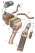
Air filter parts 1 - screw clamp; 2 - warm air supply hose; 3. - cold air supply hose; 4 - cold air supply pipe; 5 - clamping clamp; 6 - filter element; 7 -...
Air filter parts 1 - screw clamp; 2 - warm air supply hose; 3. - cold air supply hose; 4 - cold air supply pipe; 5 - clamping clamp; 6 - filter element; 7 -...

Removal and installation the air filter
Main elements of the fuel injection system 1 - sealing ring; 2 - thermal switch; 3 - nozzle; 4 - air filter housing; 5 - measuring gasket; 6 - air flow meter;...
Main elements of the fuel injection system 1 - sealing ring; 2 - thermal switch; 3 - nozzle; 4 - air filter housing; 5 - measuring gasket; 6 - air flow meter;...

Replacing the fuel filter
Execution order 1. Disconnect the wire from the negative terminal of the battery. 2. Loosen the tightening bolt of the fuel supply line (see Fig. Main elements...
Execution order 1. Disconnect the wire from the negative terminal of the battery. 2. Loosen the tightening bolt of the fuel supply line (see Fig. Main elements...
Removal and installation the fuel distributor
Execution order 1. Reduce the pressure in the fuel system (see p. 3 of subsection 6.2.2 ). 2. Mark and disconnect the fuel lines from the fuel distributor (see...
Execution order 1. Reduce the pressure in the fuel system (see p. 3 of subsection 6.2.2 ). 2. Mark and disconnect the fuel lines from the fuel distributor (see...
Disassembly and assembly of the pressure reducing valve
Execution order 1. Reduce the pressure in the fuel system (see p. 3 of subsection 6.2.2 ). 2. Unscrew the valve plug from the distributor housing (see Fig....
Execution order 1. Reduce the pressure in the fuel system (see p. 3 of subsection 6.2.2 ). 2. Unscrew the valve plug from the distributor housing (see Fig....
Removal and installation the fuel accumulator
Execution order 1. Reduce the pressure in the fuel system (see p. 3 of subsection 6.2.2 ). 2. Mark and disconnect the fuel lines from the fuel accumulator (see...
Execution order 1. Reduce the pressure in the fuel system (see p. 3 of subsection 6.2.2 ). 2. Mark and disconnect the fuel lines from the fuel accumulator (see...
Removal and installation of fuel injectors
Execution order 1. Reduce the pressure in the fuel system (see p. 3 of subsection 6.2.2 ). 2. Remove the injector holder. 3. Pull the injector upwards with the...
Execution order 1. Reduce the pressure in the fuel system (see p. 3 of subsection 6.2.2 ). 2. Remove the injector holder. 3. Pull the injector upwards with the...

Removal and installation a turbocharger
Turbocharging elements 1 - Intercooler; 2 - screw clamp; 3 - air supply hose from compressor to cooler; 4 - oil drain line; 5 - pipe supplying coolant to the...
Turbocharging elements 1 - Intercooler; 2 - screw clamp; 3 - air supply hose from compressor to cooler; 4 - oil drain line; 5 - pipe supplying coolant to the...

Removal and installation the fuel tank
Fuel tank parts for cars produced before 1988 1 - fuel pump; 2 - pump holder; 3 - fuel tank; 4 - gaskets; 5 - drain pipe; 6 - screw clamp; 7 - connecting pipe;...
Fuel tank parts for cars produced before 1988 1 - fuel pump; 2 - pump holder; 3 - fuel tank; 4 - gaskets; 5 - drain pipe; 6 - screw clamp; 7 - connecting pipe;...
Removal and installation the fuel pump
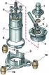
Fuel pump for cars produced before 1988 1 - silencer; 2 - gasket; 3 - fuel line; 4 - retainer; 5 - valve; 6 - electrical terminals; 7 - Electric fuel pump; 8 -...
Fuel pump for cars produced before 1988 1 - silencer; 2 - gasket; 3 - fuel line; 4 - retainer; 5 - valve; 6 - electrical terminals; 7 - Electric fuel pump; 8 -...
Checking the thermostat
Some models are equipped with a thermostat (see Fig. Air filter parts ) to control the supply of cold or warm air to the engine. Execution order 1. Loosen the...
Some models are equipped with a thermostat (see Fig. Air filter parts ) to control the supply of cold or warm air to the engine. Execution order 1. Loosen the...
Adjusting engine idle speed
The engine idle speed and CO content in the exhaust gases are maintained at a given level automatically and do not require adjustment during operation. If for...
The engine idle speed and CO content in the exhaust gases are maintained at a given level automatically and do not require adjustment during operation. If for...
Checking the starting injector
Check the starting nozzle (see Fig. Main elements of the fuel injection system ) on a cold engine (coolant temperature below 30°C) with a fully charged...
Check the starting nozzle (see Fig. Main elements of the fuel injection system ) on a cold engine (coolant temperature below 30°C) with a fully charged...
Checking the pressure regulator
The test is carried out on a cold engine. Execution order 1. Disconnect the wire from the negative terminal of the battery. 2. Disconnect the connector with...
The test is carried out on a cold engine. Execution order 1. Disconnect the wire from the negative terminal of the battery. 2. Disconnect the connector with...

Checking and adjusting the position of the air flow meter plate
Fuel injection control system of the RT engine with catalytic converter 1 - ignition distributor; 2 - coolant temperature sensor; 3 - air throttle body; 4 -...
Fuel injection control system of the RT engine with catalytic converter 1 - ignition distributor; 2 - coolant temperature sensor; 3 - air throttle body; 4 -...
This section is available on russian, bulgarian, belarusian, ukrainian, serbian, croatian, romanian, polish, slovak, hungarian
Similar sections of other Audi car models:
Power unit: Injection system (gasoline) Audi 80 B3 (1986-1991)
Power unit: Fuel injection system Audi A3 Type 8L (1996-2003)
Power unit: Injection and control system Audi A4 B6 (2000-2006, petrol)
Power unit: Injection system (gasoline) Audi A6 C5 Allroad (1999-2005)
Engine 1.2 l (diesel): Injection and turbocharging Audi A2 (1999-2005)
Power unit: Injection system (gasoline) Audi 80 B3 (1986-1991)
Power unit: Fuel injection system Audi A3 Type 8L (1996-2003)
Power unit: Injection and control system Audi A4 B6 (2000-2006, petrol)
Power unit: Injection system (gasoline) Audi A6 C5 Allroad (1999-2005)
Engine 1.2 l (diesel): Injection and turbocharging Audi A2 (1999-2005)
Share information:
- General information
- User manual
- Power unit
- Engine repair
- Ignition system
- Fuel system (gasoline)
- Fuel system (diesel)
- Lubrication system
- Cooling system
- Exhaust system
- Transmission
- Clutch
- Car gearbox
- Drive shafts
- Chassis
- Car suspension
- Steering
- Wheels and tires
- Brake system
- Body
- Ventilation and heating
- Body repair
- Electrical equipment
- Power devices
- Lighting and appliances
- Electrical circuits
- General information
- Operation and maintenance
- Power unit
- Engine repair
- Exhaust system
- Cooling system
- Supply system
- Air filter
- Mono-Motronic injection system
- Digifant injection system
- KE-III-Jetronic and KE-Motronic
- MPI and MPFI injection system
- Transmission
- Clutch
- Car gearbox
- Chassis
- Suspension and steering
- Brake system
- Wheels and tires
- Body
- Exterior
- Interior
- Electrical equipment
- Fuses and relays
- Power devices
- Ignition system
- Lighting and signaling
- Equipment and devices
- Electrical circuits
- General information
- User manual
- Maintenance
- Specifications
- Power unit
- Engines 4-cylinder
- Engines 5-cylinder
- Diesel engine
- Cooling system
- Power system (carburetor)
- Power system (injector)
- Fuel system (diesel)
- Transistor ignition system
- Electronic ignition system
- Transmission
- Clutch
- 4 speed gearbox 014
- 5 speed gearbox 013 and 093
- 5 speed gearbox 016 and 012
- Shift mechanism KP 016
- Automatic transmission
- Front wheel drive
- Chassis
- Front suspension
- Rear suspension
- Steering
- Brake system
- Body
- Body elements
- Electrical equipment
- Lighting and appliances
- Power devices
- Electrical circuits
- General information
- Maintenance and operation
- 4 cylinder engine
- Engine repair
- Cooling and lubrication system
- Supply system
- Ignition system
- 5 cylinder engine
- Engine repair
- Cooling and lubrication system
- Supply system
- Ignition system
- Transmission
- Clutch and drive shafts
- 4 speed gearbox 014
- 5 speed gearbox 013 and 093
- 5 speed gearbox 016 and 012
- Automatic gearbox
- Chassis
- Steering
- Front suspension
- Rear suspension
- Brake system
- Body
- Body elements
- Doors, locks and windows
- Body repair
- Electrical equipment
- Equipment and devices
- Power devices
- Electrical circuits
- General information
- User manual
- Maintenance
- Troubleshooting
- Power unit
- Engine in a car
- Engine removed
- Cooling system
- Fuel system
- Exhaust system
- Starting and charging
- Preheating
- Transmission
- Clutch
- Mechanical gearbox
- Automatic gearbox
- Drive shafts
- Chassis
- Brake system
- Suspension
- Steering
- Body
- Exterior
- Interior
- Electrical equipment
- Equipment and devices
- Electrical circuits