
Fuel injection control system of the RT engine with catalytic converter
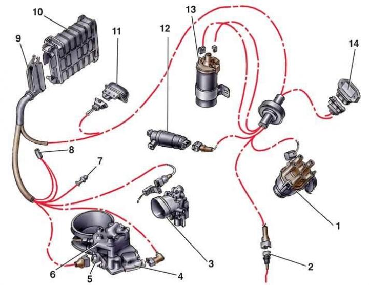
- 1 - ignition distributor;
- 2 - coolant temperature sensor;
- 3 - air throttle body;
- 4 - pressure regulator;
- 5 - potentiometer G7;
- 6 - fuel distributor;
- 7 - lambda probe connector block;
- 8 - diagnostic connector;
- 9 - junction block;
- 10 - KE-Jetronic control unit;
- 11 - altitude sensor;
- 12 - idle speed stabilizer valve;
- 13 - ignition coil;
- 14 - ignition switch
Location of the KEIII-Jetronic system installed on NF engines of cars produced since 1989
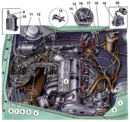
- 1 - ignition distributor;
- 2 - coolant temperature sensor;
- 3 - inlet pipe;
- 4 - idle speed stabilizer valve;
- 5 - carbon filter valve;
- 6 - pressure regulator;
- 7 - fuel distributor;
- 8 - potentiometer;
- 9 - junction block;
- 10 - KEIII-Jetronic control unit;
- 11 - fuel filter;
- 12 - air throttle body;
- 13 - starting nozzle;
- 14 - ignition coil;
- 15 - knock sensor;
- 16 - Lambda probe connector block;
- 17 - Lambda probe heating connector;
- 18 - knock sensor connector;
- 19 - ignition switch;
- 20 - altitude sensor
Fuel Shutoff Circuit
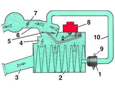
- 1 - engine braking valve;
- 2 - air filter;
- 3 - air intake pipe;
- 4 - air flow meter;
- 5 - measuring plate;
- 6 - air duct;
- 7 - throttle valve;
- 8 - fuel distributor;
- 9 - vacuum tube connection branch pipe;
- 10 - bypass hose
The height of the plate lift depends on the amount of air supplied to the engine cylinders: the greater the air flow, the higher the plate rises. In this case, the plate lever presses the plunger of the fuel distributor, which leads to an increase in the amount of fuel supplied to the cylinders. When the air flow decreases, the plate goes down, the plate lever in turn lowers the plunger and the fuel supply decreases. At an engine speed of no more than 1400 min⁻¹, a coolant temperature of no more than 30°C and the throttle valve in the idle position, the valve is turned on and air goes through the bypass hose, bypassing the air flow meter. The plate goes down, releasing the plunger, and the fuel supply is turned off until the valve closes. For better mixture formation, the plate should be located exactly in the center of the diffuser.
Execution order
1. Loosen the clamps and remove the air duct (see Fig. Main elements of the fuel injection system).
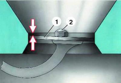
2. If the plate (1) is displaced, loosen the screw (2). Center the plate using a 0.1 mm thick feeler gauge, inserting it around the plate. Tighten the screw.
3. Raise and quickly lower the plate. There should be no resistance when moving downwards. If resistance is felt, the air flow meter is faulty and needs to be replaced.
4. If resistance is felt when the plate moves up, you need to remove the fuel distributor, take out and wash the plunger in gasoline. If this does not help, replace the fuel distributor.
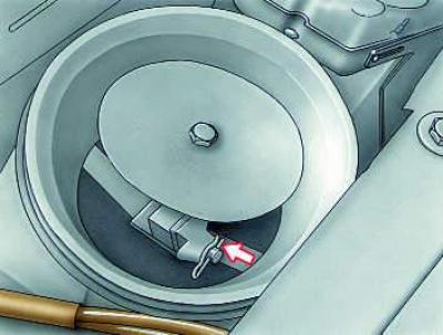
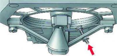
5. Check the height of the plate relative to the diffuser. The gap between the upper edge of the plate and the edge of the cylindrical part of the diffuser (marked with arrows) should be: for engines with the K-Jetronic system 0–0.5 mm, for engines of the KZ models 1.75–2.05 mm, for engines with the high-pressure K-Jetronic system and KE-Jetronic (in these engines, fuel is supplied to the injectors through metal tubes) 1.9–3.0 mm. To adjust the height of the plate for engines with the K-Jetronic and KZ systems, remove the air duct (see Fig. Main elements of the fuel injection system), lift the plate and bend or compress the wire clip located underneath it, as shown in the figure on the left. For other engines, remove the filter cover with the filter element and adjust the position of the plate by turning the nut on the plate stop screw, as shown in the figure on the right.