



Vehicle equipment and devices Audi 100 C3, petrol

Detailed technical characteristics of electrical equipment
The electrical equipment is made according to a single-wire scheme. The negative terminals of consumers and power sources are connected to the "ground", which...
The electrical equipment is made according to a single-wire scheme. The negative terminals of consumers and power sources are connected to the "ground", which...

Lamps used in the car
Installation location Power, W Low/high beam headlights (H4 bulb) 55/60 Front side light 4 Direction indicators 21 Fog lights (K3) 55 Rear fog light 21 Stop...
Installation location Power, W Low/high beam headlights (H4 bulb) 55/60 Front side light 4 Direction indicators 21 Fog lights (K3) 55 Rear fog light 21 Stop...

Fuses — location and ratings
The fuses are located in the mounting block installed in the air intake box on the left side of the power unit compartment. Fuse box arrangement diagram fuse...
The fuses are located in the mounting block installed in the air intake box on the left side of the power unit compartment. Fuse box arrangement diagram fuse...

Relay — location and designation
Depending on the modification and version of the electrical equipment, the number of relays may vary significantly. The relays are located in the mounting...
Depending on the modification and version of the electrical equipment, the number of relays may vary significantly. The relays are located in the mounting...
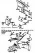
Windscreen wiper and washer parts
Windscreen wiper and washer parts: 1 - brush lever; 2 - brush; 3 - windshield wiper motor; 4 - axle with bushing of right wiper arm; 5 - wasp with bushing of...
Windscreen wiper and washer parts: 1 - brush lever; 2 - brush; 3 - windshield wiper motor; 4 - axle with bushing of right wiper arm; 5 - wasp with bushing of...

Removal and installation the windshield wiper
Disconnect the wire from the negative terminal of the battery. Remove both brush arms. Remove the wiper motor protective cover. Removal the windshield wiper...
Disconnect the wire from the negative terminal of the battery. Remove both brush arms. Remove the wiper motor protective cover. Removal the windshield wiper...

Removal and installation the instrument cluster
Disconnect the wire from the negative terminal of the battery. Manually separate the steering wheel trim cover. Disconnect the horn connector. Loosen the...
Disconnect the wire from the negative terminal of the battery. Manually separate the steering wheel trim cover. Disconnect the horn connector. Loosen the...

Location of lamps in the instrument cluster
Location of lamps in the instrument cluster: 1 - ABS malfunction indicator lamp; 2 - seat belt unfastened indicator light; 3 - Low coolant temperature...
Location of lamps in the instrument cluster: 1 - ABS malfunction indicator lamp; 2 - seat belt unfastened indicator light; 3 - Low coolant temperature...

Purpose of plugs in instrument cluster connectors
plug No Purpose of the plug 14-pin connector 1 "+" of digital or analog watches 2 "-" of the pointer clock and control lamps 3 "+" of the hazard warning light...
plug No Purpose of the plug 14-pin connector 1 "+" of digital or analog watches 2 "-" of the pointer clock and control lamps 3 "+" of the hazard warning light...

Checking the coolant temperature and fuel level gauges
Incorrect operation of the coolant temperature and fuel level indicators may be due to a lack of supply voltage to the voltage stabilizer, which is installed...
Incorrect operation of the coolant temperature and fuel level indicators may be due to a lack of supply voltage to the voltage stabilizer, which is installed...

Instrument cluster details
Instrument cluster details: 1 - visor; 2 - Instrument panel cover; 3 - control lamp symbol bar; 4 - fuel level indicator; 5 - Instrument lighting switch; 6 -...
Instrument cluster details: 1 - visor; 2 - Instrument panel cover; 3 - control lamp symbol bar; 4 - fuel level indicator; 5 - Instrument lighting switch; 6 -...

Headlight adjustment
It is best to adjust the headlights using movable optical devices. If they are not available, adjustment can be made using the screen. To adjust the light beam...
It is best to adjust the headlights using movable optical devices. If they are not available, adjustment can be made using the screen. To adjust the light beam...
This section is available on russian, bulgarian, belarusian, ukrainian, serbian, croatian, romanian, polish, slovak, hungarian
Similar sections of other Audi car models:
Electrical equipment: Lighting and appliances Audi 80 B3 (1986-1991)
Electrical equipment: Lighting and appliances Audi A3 Type 8L (1996-2003)
Electrical equipment: Lighting and appliances Audi A4 B6 (2000-2006)
Electrical equipment: Lighting and appliances Audi A6 C4 (1994-1997)
Electrical equipment: Lighting and appliances Audi 80 B3 (1986-1991)
Electrical equipment: Lighting and appliances Audi A3 Type 8L (1996-2003)
Electrical equipment: Lighting and appliances Audi A4 B6 (2000-2006)
Electrical equipment: Lighting and appliances Audi A6 C4 (1994-1997)
Share information:
- General information
- User manual
- Power unit
- Engine repair
- Ignition system
- Fuel system (gasoline)
- Fuel system (diesel)
- Lubrication system
- Cooling system
- Exhaust system
- Transmission
- Clutch
- Car gearbox
- Drive shafts
- Chassis
- Car suspension
- Steering
- Wheels and tires
- Brake system
- Body
- Ventilation and heating
- Body repair
- Electrical equipment
- Power devices
- Lighting and appliances
- Electrical circuits
- General information
- Operation and maintenance
- Power unit
- Engine repair
- Exhaust system
- Cooling system
- Supply system
- Air filter
- Mono-Motronic injection system
- Digifant injection system
- KE-III-Jetronic and KE-Motronic
- MPI and MPFI injection system
- Transmission
- Clutch
- Car gearbox
- Chassis
- Suspension and steering
- Brake system
- Wheels and tires
- Body
- Exterior
- Interior
- Electrical equipment
- Fuses and relays
- Power devices
- Ignition system
- Lighting and signaling
- Equipment and devices
- Electrical circuits
- General information
- User manual
- Maintenance
- Specifications
- Power unit
- Engines 4-cylinder
- Engines 5-cylinder
- Diesel engine
- Cooling system
- Power system (carburetor)
- Power system (injector)
- Fuel system (diesel)
- Transistor ignition system
- Electronic ignition system
- Transmission
- Clutch
- 4 speed gearbox 014
- 5 speed gearbox 013 and 093
- 5 speed gearbox 016 and 012
- Shift mechanism KP 016
- Automatic transmission
- Front wheel drive
- Chassis
- Front suspension
- Rear suspension
- Steering
- Brake system
- Body
- Body elements
- Electrical equipment
- Lighting and appliances
- Power devices
- Electrical circuits
- General information
- Maintenance and operation
- 4 cylinder engine
- Engine repair
- Cooling and lubrication system
- Supply system
- Ignition system
- 5 cylinder engine
- Engine repair
- Cooling and lubrication system
- Supply system
- Ignition system
- Transmission
- Clutch and drive shafts
- 4 speed gearbox 014
- 5 speed gearbox 013 and 093
- 5 speed gearbox 016 and 012
- Automatic gearbox
- Chassis
- Steering
- Front suspension
- Rear suspension
- Brake system
- Body
- Body elements
- Doors, locks and windows
- Body repair
- Electrical equipment
- Equipment and devices
- Power devices
- Electrical circuits
- General information
- User manual
- Maintenance
- Troubleshooting
- Power unit
- Engine in a car
- Engine removed
- Cooling system
- Fuel system
- Exhaust system
- Starting and charging
- Preheating
- Transmission
- Clutch
- Mechanical gearbox
- Automatic gearbox
- Drive shafts
- Chassis
- Brake system
- Suspension
- Steering
- Body
- Exterior
- Interior
- Electrical equipment
- Equipment and devices
- Electrical circuits