Repair Chevrolet Repair Toyota Repair Honda Repair AvtoVAZ Repair Mercedes-Benz Repair BMW Repair Opel
Home  |  Contacts  |  Sitemap  |    
English Русский
Български
Беларускі
Український
Српски
Hrvatski
Română
Polski
Slovenský
Magyar
AudiManual.ru


  • AUDI 80
  • AUDI 100
  • AUDI A3
  • AUDI A4
  • AUDI A6
  • AUDI A8
  • AUDI Q
  • OTHER
  • ARTICLES
C4 (1990-1994) C4 (1990-1994, petrol) C3 (1982-1990) C3 (1982-1990, petrol) C3 (1982-1990, diesel)

Checking the coolant temperature and fuel level gauges (Audi 100 C3)

  • Home
  • Audi 100
  • C3 (1982-1990, petrol)
  • Electrical equipment
  • Equipment and devices
  • Checking the coolant temperature and fuel level gauges
            0
Table of contents: Fuel level indicator ↓ Adjusting the fuel gauge ↓
Incorrect operation of the coolant temperature and fuel level indicators may be due to a lack of supply voltage to the voltage stabilizer, which is installed on the back of the instrument cluster, on the left side of the printed circuit board.

First of all, check the presence of voltage supply to the stabilizer by connecting a voltmeter between its input and the "ground", the value of which should be almost equal to the voltage of the battery.

Then measure the output voltage of the stabilizer between the "ground" and its output, which should be within 9.75-10.25 V. If the obtained output voltage does not correspond to the norm, replace the voltage stabilizer.

Fuel level indicator


Markings on the fuel gauge scale: A - «empty tank» position; B - «full tank» position

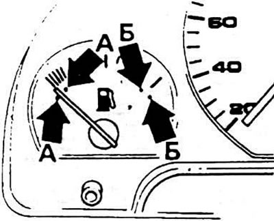
Markings on the fuel gauge scale: A - "empty tank" position; B - "full tank" position


If the device malfunctions, check the sensor installed in the fuel tank for proper operation. To do this, never connect the indicator wire directly to the "ground". The check is performed by connecting a resistor between the two plugs of the sensor connector.


When a 544 Ohm resistor is connected, the pointer should be at the beginning of the scale (the "empty tank" position), and when a 60 Ohm resistor is connected, it should move to the end of the scale (the "full tank" position). Each of these positions of the pointer is marked on the scale with two dots indicating the tolerance. If the pointer does not occupy the same position relative to the marks at the beginning and end of the scale, adjust the pointer as indicated below. If this can be done, replace the sensor. If the difference in the position of the pointer between the marks remains significant, check the supply voltage of the device and, if necessary, replace it.

Adjusting the fuel gauge


Fill the completely empty tank with 12 liters of fuel. Turn on the ignition (and do this at least 2 minutes before adjusting the pointer): the arrow should be on the right edge of the red zone of the scale. If not, adjust the device with the adjusting screw underneath it.

[The original article is available on the website audimanual.ru]
The article was checked by auto expert Maxim Rybakov
This article is available at russian, bulgarian, belarusian, ukrainian, serbian, croatian, romanian, polish, slovak, hungarian

Share information:
Previous articles
Audi 100 C3: Equipment and devices
Next articles

Purpose of plugs in instrument cluster connectors
Location of lamps in the instrument cluster
Removal and installation the instrument cluster
Removal and installation the windshield wiper
Instrument cluster details
Headlight adjustment


Similar articles on other Audi car models:
Coolant — Checking the Level Audi 80 B4 (1991-1996)
Checking the fuel system Audi A3 Type 8L (1996-2003)
Checking the coolant level Audi A4 B5 (1994-2001, petrol)
Wiring diagram of the instrument cluster display, control lamps,… Audi A6 C5 (1997-2004)
Checking the oil level in a manual transmission Audi A8 D2 (1994-2002)
Checking the fuel level sensor «G» Audi Q5 Type 8R (2008-2017)
Engine — Checking Oil Level Audi A2 (1999-2005)
Link to this page in different formats


Visitor comments

No comments yet


How much will 33 + 38 =


100(C4, 1990-1994) 
  • General information
  • User manual
  • Power unit
  • Engine repair
  • Ignition system
  • Fuel system (gasoline)
  • Fuel system (diesel)
  • Lubrication system
  • Cooling system
  • Exhaust system
  • Transmission
  • Clutch
  • Car gearbox
  • Drive shafts
  • Chassis
  • Car suspension
  • Steering
  • Wheels and tires
  • Brake system
  • Body
  • Ventilation and heating
  • Body repair
  • Electrical equipment
  • Power devices
  • Lighting and appliances
  • Electrical circuits
 
100(C4, 1990-1994, petrol) 
  • General information
  • Operation and maintenance
  • Power unit
  • Engine repair
  • Exhaust system
  • Cooling system
  • Supply system
  • Air filter
  • Mono-Motronic injection system
  • Digifant injection system
  • KE-III-Jetronic and KE-Motronic
  • MPI and MPFI injection system
  • Transmission
  • Clutch
  • Car gearbox
  • Chassis
  • Suspension and steering
  • Brake system
  • Wheels and tires
  • Body
  • Exterior
  • Interior
  • Electrical equipment
  • Fuses and relays
  • Power devices
  • Ignition system
  • Lighting and signaling
  • Equipment and devices
  • Electrical circuits
 
100(C3, 1982-1990) 
  • General information
  • User manual
  • Maintenance
  • Specifications
  • Power unit
  • Engines 4-cylinder
  • Engines 5-cylinder
  • Diesel engine
  • Cooling system
  • Power system (carburetor)
  • Power system (injector)
  • Fuel system (diesel)
  • Transistor ignition system
  • Electronic ignition system
  • Transmission
  • Clutch
  • 4 speed gearbox 014
  • 5 speed gearbox 013 and 093
  • 5 speed gearbox 016 and 012
  • Shift mechanism KP 016
  • Automatic transmission
  • Front wheel drive
  • Chassis
  • Front suspension
  • Rear suspension
  • Steering
  • Brake system
  • Body
  • Body elements
  • Electrical equipment
  • Lighting and appliances
  • Power devices
  • Electrical circuits
 
100(C3, 1982-1990, petrol) 
  • General information
  • Maintenance and operation
  • 4 cylinder engine
  • Engine repair
  • Cooling and lubrication system
  • Supply system
  • Ignition system
  • 5 cylinder engine
  • Engine repair
  • Cooling and lubrication system
  • Supply system
  • Ignition system
  • Transmission
  • Clutch and drive shafts
  • 4 speed gearbox 014
  • 5 speed gearbox 013 and 093
  • 5 speed gearbox 016 and 012
  • Automatic gearbox
  • Chassis
  • Steering
  • Front suspension
  • Rear suspension
  • Brake system
  • Body
  • Body elements
  • Doors, locks and windows
  • Body repair
  • Electrical equipment
  • Equipment and devices
  • Power devices
  • Electrical circuits
 
100(C3, 1982-1990, diesel) 
  • General information
  • User manual
  • Maintenance
  • Troubleshooting
  • Power unit
  • Engine in a car
  • Engine removed
  • Cooling system
  • Fuel system
  • Exhaust system
  • Starting and charging
  • Preheating
  • Transmission
  • Clutch
  • Mechanical gearbox
  • Automatic gearbox
  • Drive shafts
  • Chassis
  • Brake system
  • Suspension
  • Steering
  • Body
  • Exterior
  • Interior
  • Electrical equipment
  • Equipment and devices
  • Electrical circuits
 
AudiManual.ru © 2017-2026 · Mobile version · Feedback · Sitemap: EN BG BY UA RS HR RO PL SK HU · Site search · News and articles
80 B2 · 80 B3 petrol · 80 B3 · 80 B4 · 100 C3 diesel · 100 C3 petrol · 100 C3 · 100 C4 petrol · 100 C4 · A3 Type 8L · A4 B5 petrol · A4 B5 · A4 B6 petrol · A4 B6 · A4 B7 · A4 B8 · A6 C4 · A6 C5 · A6 C5 Allroad · A8 D2 · Q5 Type 8R · Q7 Typ 4L · Audi A2 ·
This site uses cookies 🍪. Click the button to accept this fact.