



4-cylinder car engines Audi 100 C3
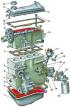
The structure of a four-cylinder engine
Four-cylinder engine 1 - oil pan; 2 - crankcase gasket; 3 - water pump; 4 - generator mounting bolt; 5 - key; 6 - water pump sealing ring; 7 - cylinder head...
Four-cylinder engine 1 - oil pan; 2 - crankcase gasket; 3 - water pump; 4 - generator mounting bolt; 5 - key; 6 - water pump sealing ring; 7 - cylinder head...

Removal and installation the engine
Execution order 1. Position the vehicle over an inspection pit so that the engine is under a hoist or other similar device with a lifting capacity of at least...
Execution order 1. Position the vehicle over an inspection pit so that the engine is under a hoist or other similar device with a lifting capacity of at least...
Disassembly and assembly of the engine
Before disassembling, the engine must be thoroughly cleaned of dirt, installed on a stand, and if there is no stand, on an appropriate support, while the...
Before disassembling, the engine must be thoroughly cleaned of dirt, installed on a stand, and if there is no stand, on an appropriate support, while the...

Removal and installation the cylinder head
Cylinder Head Bolt Tightening Sequence The engine has been removed from the car 1. Remove the top cover 8 (see Fig. Camshaft Drive Parts ) camshaft drive. 2....
Cylinder Head Bolt Tightening Sequence The engine has been removed from the car 1. Remove the top cover 8 (see Fig. Camshaft Drive Parts ) camshaft drive. 2....

Removal the camshaft and valve lifters
Cylinder head, camshaft and valves 1 - exhaust valve; 2 - inlet valve; 3 - gasket; 4 - internal valve spring; 5 - outer valve spring; 6 - valve spring plate; 7...
Cylinder head, camshaft and valves 1 - exhaust valve; 2 - inlet valve; 3 - gasket; 4 - internal valve spring; 5 - outer valve spring; 6 - valve spring plate; 7...
Inspection of the camshaft
Execution order 1. Thoroughly wash all parts in gasoline or diesel fuel, wipe and dry. 2. Inspect the cams and journals of the camshaft. If the cams and...
Execution order 1. Thoroughly wash all parts in gasoline or diesel fuel, wipe and dry. 2. Inspect the cams and journals of the camshaft. If the cams and...
Determination of the technical condition of hydraulic valve lifters
Hydraulic tappets have a non-separable design and cannot be repaired. Execution order 1. Start and warm up the engine. Let it run until the fan turns on. 2....
Hydraulic tappets have a non-separable design and cannot be repaired. Execution order 1. Start and warm up the engine. Let it run until the fan turns on. 2....
Installing the camshaft and valve lifters
Execution order 1. Lubricate the camshaft cams, journals and tappets with engine oil. 2. Install adjusting washers 8 into the pushers 7 with the inscription...
Execution order 1. Lubricate the camshaft cams, journals and tappets with engine oil. 2. Install adjusting washers 8 into the pushers 7 with the inscription...
Removal and installation valves (disassembling the cylinder head)
Counting from the camshaft drive, valves No.1, 3, 6, 8 are exhaust valves, and valves No.2, 4, 5, 7 are intake valves. Execution order 1. Using a special tool,...
Counting from the camshaft drive, valves No.1, 3, 6, 8 are exhaust valves, and valves No.2, 4, 5, 7 are intake valves. Execution order 1. Using a special tool,...

Inspection, defect detection and repair of cylinder head parts
Four-cylinder engine valve dimensions inlet valve exhaust valve a 40.0 mm 33.0 mm b 7.97 mm 7.95 mm with 91 mm 90.8 mm Valve seat dimensions Valve seat...
Four-cylinder engine valve dimensions inlet valve exhaust valve a 40.0 mm 33.0 mm b 7.97 mm 7.95 mm with 91 mm 90.8 mm Valve seat dimensions Valve seat...
Clearances between camshaft lobes and valve lifters
Clearances between camshaft lobes and valve tappets (engines of DR and DS models produced before September 1985.) are adjusted using adjusting washers, which...
Clearances between camshaft lobes and valve tappets (engines of DR and DS models produced before September 1985.) are adjusted using adjusting washers, which...

Camshaft drive
Camshaft Drive Parts 1 - water pump pulley; 2 - water pump pulley mounting bolt; 3 - crankshaft pulley mounting bolt; 4 - crankshaft pulley; 5 - belt; 6 -...
Camshaft Drive Parts 1 - water pump pulley; 2 - water pump pulley mounting bolt; 3 - crankshaft pulley mounting bolt; 4 - crankshaft pulley; 5 - belt; 6 -...
Removal and installation the flywheel
On cars with an automatic transmission, a drive disk is installed instead of a flywheel. The procedure for removing the flywheel and the drive disk is the...
On cars with an automatic transmission, a drive disk is installed instead of a flywheel. The procedure for removing the flywheel and the drive disk is the...
Replacing crankshaft seals
Front oil seal 1. Remove the camshaft drive belt and crankshaft sprocket (see pp. 1–10 of subsection 3.1.2.9) . 2. Unscrew the bolts securing the holder 6 of...
Front oil seal 1. Remove the camshaft drive belt and crankshaft sprocket (see pp. 1–10 of subsection 3.1.2.9) . 2. Unscrew the bolts securing the holder 6 of...
Removal and installation the oil pan
Execution order 1. Drain the oil from the engine crankcase. 2. Remove the pan covering the gearbox. 3. Place a jack under the front suspension beam. 4. Loosen...
Execution order 1. Drain the oil from the engine crankcase. 2. Remove the pan covering the gearbox. 3. Place a jack under the front suspension beam. 4. Loosen...

Removal, checking and installation the oil pump
Execution order 1. Remove the oil pan (see pp. 1–5 of subsection 3.1.2.13) . 2. Loosen the mounting bolts and remove the oil pump with the oil receiver. 3....
Execution order 1. Remove the oil pan (see pp. 1–5 of subsection 3.1.2.13) . 2. Loosen the mounting bolts and remove the oil pump with the oil receiver. 3....

Disassembling the connecting rod and piston group
Crankshaft and connecting rod and piston group parts 1 - crankshaft; 2 - connecting rod bearing shell; 3 - connecting rod bolt; 4 - finger; 5 - oil scraper...
Crankshaft and connecting rod and piston group parts 1 - crankshaft; 2 - connecting rod bearing shell; 3 - connecting rod bolt; 4 - finger; 5 - oil scraper...
Inspection and testing of connecting rod and piston group parts
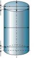
Cylinder Diameter Measurement Diagram A, B - directions of measurements 1, 2, 3 - measurement belts Piston Identification a = 8.1 mm, mod. DR a = 4.4 mm, mod....
Cylinder Diameter Measurement Diagram A, B - directions of measurements 1, 2, 3 - measurement belts Piston Identification a = 8.1 mm, mod. DR a = 4.4 mm, mod....
Assembly of the connecting rod and piston group
Execution order 1. Heat the piston 7 (see fig. Crankshaft and connecting rod and piston group parts ), placing it for 2–3 minutes in water heated to a...
Execution order 1. Heat the piston 7 (see fig. Crankshaft and connecting rod and piston group parts ), placing it for 2–3 minutes in water heated to a...
Removal, inspection and installation of the crankshaft
Execution order 1. Remove the connecting rod and piston group (cm. subsection 3.1.2.15 ). 2. Remove the crankshaft oil seal covers with oil seals (see p. 2 of...
Execution order 1. Remove the connecting rod and piston group (cm. subsection 3.1.2.15 ). 2. Remove the crankshaft oil seal covers with oil seals (see p. 2 of...

Removal and installation the intermediate shaft
Crankshaft and cylinder block 1 - upper thrust half ring; 2 - intermediate shaft seal; 3 - gland flange; 4 - intermediate shaft; 5 - crankshaft oil seal; 6 -...
Crankshaft and cylinder block 1 - upper thrust half ring; 2 - intermediate shaft seal; 3 - gland flange; 4 - intermediate shaft; 5 - crankshaft oil seal; 6 -...
This section is available on russian, bulgarian, belarusian, ukrainian, serbian, croatian, romanian, polish, slovak, hungarian
Similar sections of other Audi car models:
Power unit: Engine 5-cylinder Audi 80 B3 (1986-1991, petrol)
Power unit: Engine repair Audi A3 Type 8L (1996-2003)
Power unit: Engine repair Audi A4 B6 (2000-2006, petrol)
Gasoline engines: 6 cylinder engines Audi A6 C4 (1994-1997)
Engine 1.2 l (diesel): Engine repair Audi A2 (1999-2005)
Power unit: Engine 5-cylinder Audi 80 B3 (1986-1991, petrol)
Power unit: Engine repair Audi A3 Type 8L (1996-2003)
Power unit: Engine repair Audi A4 B6 (2000-2006, petrol)
Gasoline engines: 6 cylinder engines Audi A6 C4 (1994-1997)
Engine 1.2 l (diesel): Engine repair Audi A2 (1999-2005)
Share information:
- General information
- User manual
- Power unit
- Engine repair
- Ignition system
- Fuel system (gasoline)
- Fuel system (diesel)
- Lubrication system
- Cooling system
- Exhaust system
- Transmission
- Clutch
- Car gearbox
- Drive shafts
- Chassis
- Car suspension
- Steering
- Wheels and tires
- Brake system
- Body
- Ventilation and heating
- Body repair
- Electrical equipment
- Power devices
- Lighting and appliances
- Electrical circuits
- General information
- Operation and maintenance
- Power unit
- Engine repair
- Exhaust system
- Cooling system
- Supply system
- Air filter
- Mono-Motronic injection system
- Digifant injection system
- KE-III-Jetronic and KE-Motronic
- MPI and MPFI injection system
- Transmission
- Clutch
- Car gearbox
- Chassis
- Suspension and steering
- Brake system
- Wheels and tires
- Body
- Exterior
- Interior
- Electrical equipment
- Fuses and relays
- Power devices
- Ignition system
- Lighting and signaling
- Equipment and devices
- Electrical circuits
- General information
- User manual
- Maintenance
- Specifications
- Power unit
- Engines 4-cylinder
- Engines 5-cylinder
- Diesel engine
- Cooling system
- Power system (carburetor)
- Power system (injector)
- Fuel system (diesel)
- Transistor ignition system
- Electronic ignition system
- Transmission
- Clutch
- 4 speed gearbox 014
- 5 speed gearbox 013 and 093
- 5 speed gearbox 016 and 012
- Shift mechanism KP 016
- Automatic transmission
- Front wheel drive
- Chassis
- Front suspension
- Rear suspension
- Steering
- Brake system
- Body
- Body elements
- Electrical equipment
- Lighting and appliances
- Power devices
- Electrical circuits
- General information
- Maintenance and operation
- 4 cylinder engine
- Engine repair
- Cooling and lubrication system
- Supply system
- Ignition system
- 5 cylinder engine
- Engine repair
- Cooling and lubrication system
- Supply system
- Ignition system
- Transmission
- Clutch and drive shafts
- 4 speed gearbox 014
- 5 speed gearbox 013 and 093
- 5 speed gearbox 016 and 012
- Automatic gearbox
- Chassis
- Steering
- Front suspension
- Rear suspension
- Brake system
- Body
- Body elements
- Doors, locks and windows
- Body repair
- Electrical equipment
- Equipment and devices
- Power devices
- Electrical circuits
- General information
- User manual
- Maintenance
- Troubleshooting
- Power unit
- Engine in a car
- Engine removed
- Cooling system
- Fuel system
- Exhaust system
- Starting and charging
- Preheating
- Transmission
- Clutch
- Mechanical gearbox
- Automatic gearbox
- Drive shafts
- Chassis
- Brake system
- Suspension
- Steering
- Body
- Exterior
- Interior
- Electrical equipment
- Equipment and devices
- Electrical circuits