
Cylinder Diameter Measurement Diagram
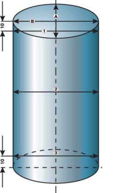
- A, B - directions of measurements
- 1, 2, 3 - measurement belts
Piston Identification
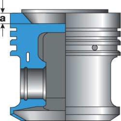
- a = 8.1 mm, mod. DR
- a = 4.4 mm, mod. DS
Execution order
1. All parts of the connecting rod and piston group must be cleaned and washed with gasoline.
2. Inspect the pistons. Measure the diameter of the piston skirt at a distance of 15 mm from the lower edge of the skirt perpendicular to the axis of the piston pin. The piston must be replaced if the measured diameter differs by 0.04 mm from the nominal diameter of 80.98 mm. To measure the gap in the piston ring lock, insert the ring into the cylinder and push it with the piston, like a mandrel, to a distance of 15 mm from the base of the cylinder. Measure the gap in the lock with a feeler gauge. If the gap exceeds 1.0 mm, the rings must be replaced.
3. Measure the side clearance between the piston rings and the grooves on the piston in several places around the circumference. If the clearance exceeds 0.15 mm, replace the rings or pistons.
4. Use a bore gauge to measure the diameter of the cylinders as shown in the figure Cylinder Diameter Measurement Diagram. The diameter of each cylinder is measured at six points, 10 mm from the lower edge of the cylinder, 10 mm from the upper edge of the cylinder and in the middle in two perpendicular directions. If the wear from the nominal diameter of 81.01 mm exceeds 0.08 mm, bore the cylinders to the repair size. If the wear reaches the limit in only one cylinder, all four cylinders must still be bored, otherwise the engine will not be balanced.