
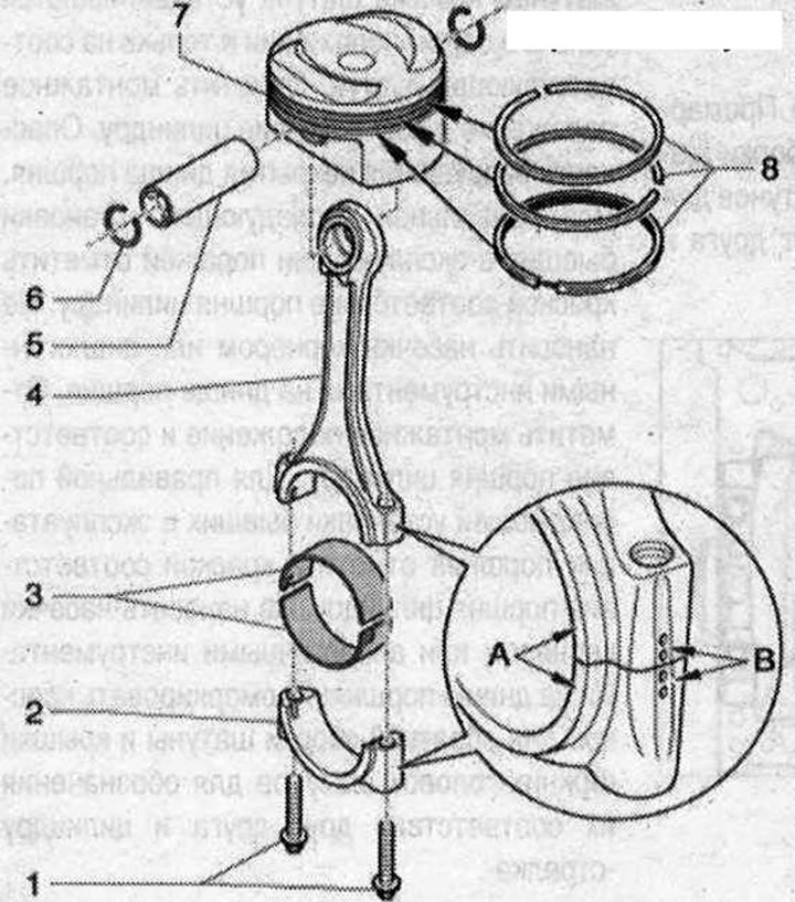
Pistons and connecting rods 1. Bolts. Replace. Lubricate the threads and contact surface with oil. 30 Nm + additional rotation by 90°; 2. Connecting rod head cover. Mark for reassembly. Mark the correspondence to the cylinder with a colored pencil -B-. When installing the bearing cap, note the following: the wide adjusting collar -A- must point in the same direction, both on the connecting rod and on the connecting rod cap; 3. Bearing shell. Ensure that the locking lugs are firmly seated. Mark previously used inserts, but not on the work surface. Replace bearing shells worn down to the original material; 4. Connecting rod. Replace only the entire set. Mark the correspondence to the cylinder with a colored pencil -B-. When installing the bearing cap, note the following: the wide adjusting collar -A- must point in the same direction, both on the connecting rod and on the connecting rod cap; 5. Piston pin. If the pin is difficult to install, then heat the piston to 60°C. Remove and install using a mandrel -VW 222 A-; 6. Retaining ring. Replace; 7. Piston. Mark the installation position and cylinder accessory. The arrow on the piston crown points towards the belt pulley. Check. Install using a piston ring clamp. Measure the internal diameter of the cylinder; 8. Piston rings. Place locks offset by 120°. Remove and install using piston ring pliers. Mounting position: mark "TOP" or the inscribed side faces the piston crown
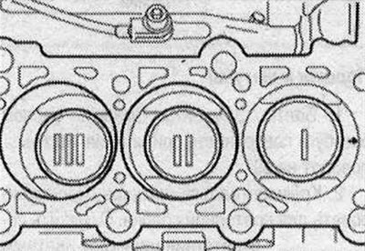
Piston mounting position
Carefully! Risk of destruction of the piston crown coating. To ensure correct subsequent installation of used pistons, mark the piston to cylinder with paint. Do not score the piston crown with a center punch or similar tools.
Installation position: The arrows on the piston crowns point towards the belt pulleys.
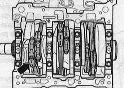
Mark connecting rods
Replace the connecting rod only as an assembly. Mark connecting rods and connecting rod lower end caps with reassembly paint to indicate their alignment with each other and with the cylinder -arrow-.
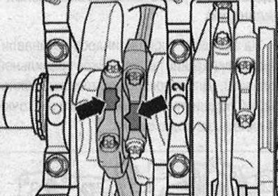
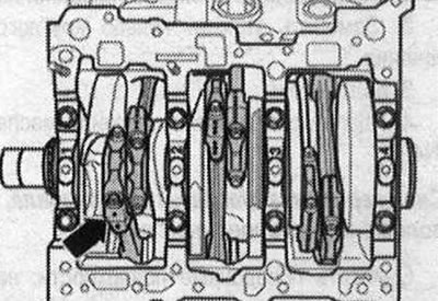
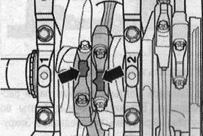
Connecting rod mounting position
Toes -arrows- on the ground surfaces of pairs of connecting rods "1 and 2", "3 and 4", and "5 and 6" must be addressed to each other -
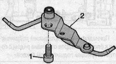
Piston cooling oil nozzle 1. Insert a bolt with thread varnish and tighten to a torque of 9 Nm; 2. Oil injection nozzle with valve (opening at excess pressure 2...2.4 bar)
Note. Do not bend the oil nozzles to spray oil. Curved oil spray nozzles must be replaced.
Removing the piston
Remove the engine. Attach the engine to the mounting stand. Remove the cylinder heads. Remove the top of the oil pan. Thanks to the constructive fracture method (cracking) For connecting rods, the connecting rod cap is installed in only one position and only on the corresponding connecting rod. Mark the installation position and correspondence to the cylinder. Risk of destruction of the piston crown coating. To ensure correct subsequent installation of used pistons, mark the piston to cylinder with paint. Do not score the piston crown with a center punch or similar tools. Mark the installation position and the correspondence of the piston to the cylinder. To ensure correct subsequent installation of used pistons, mark the piston to cylinder with paint. Do not score the piston crown with a center punch or similar tools. Mark connecting rods and connecting rod lower end caps with reassembly paint to indicate their alignment with each other and with the cylinder -arrow-.
Remove the connecting rod head cover and remove the piston and connecting rod upwards. If the piston bolt stroke is difficult, heat the piston to approximately 60°C. Remove the circlip from the piston pin seat and remove the piston pin using a bit -VW 222 A-.
Installation
Install in the reverse order, taking into account the tightening torque. The arrow on the piston crown points towards the belt pulley. Move the piston ring lock 120°. Lubricate the working surface of the liners with oil. Install the pistons using a standard piston ring tensioning band, taking into account the installation position. Toes -arrows- on the ground surfaces of pairs of connecting rods "1 and 2", "3 and 4", and "5 and 6" should be facing each other.
Install the connecting rod head cover, taking into account the installation position. Install the cylinder heads. Install the upper part of the oil pan. Install the engine.
Visitor comments