
Disconnecting the engine and gearbox 0B6
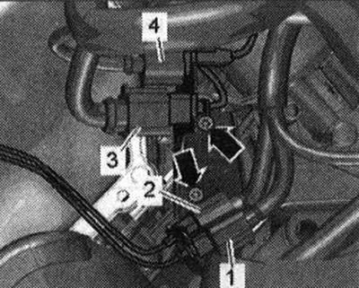
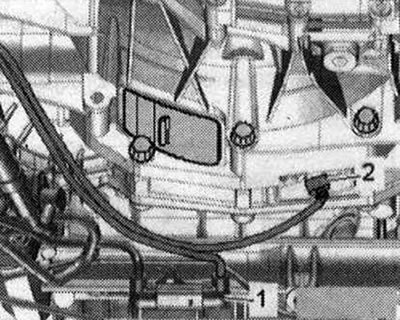
The power unit has been removed and installed on the lifting table -VAS 6131. A-. Remove plug connector -1- for lambda probe 2 after catalytic converter -G131- from holder, disconnect and place to one side. -Pos. 2,3, 4- and -arrows- are ignored.
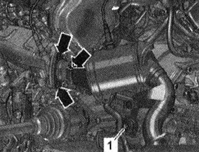
Unscrew nuts -arrows- and bolt -1- and remove left catalytic converter.
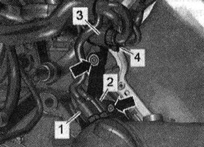
Remove and disconnect electrical connector -1- for lambda probe after catalytic converter -G130- from holder. Release el. plug connection -2- from the holder. Unscrew the bolts -arrows- and set the bracket with the electrical parts aside. connectors -3- and -4-.
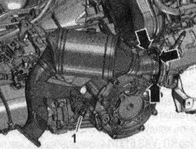
Unscrew nuts -arrows- and bolt -1- and remove right catalytic converter.
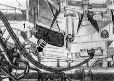
Disconnect electrical connector -2- from engine speed sender -G28- and lay electrical cable to one side. -Pos. 1- do not take into account.
Risk of gearbox control unit malfunction (Mechatronik) due to static discharge. Do not touch the contacts of the gearbox plug with your hands. To remove static tension, touch with your hand (without gloves) gearbox housing Disconnect el. plug connection from the gearbox by turning the rotary bolt counterclockwise -arrow-. Release the wiring harness from the mountings on the gearbox.
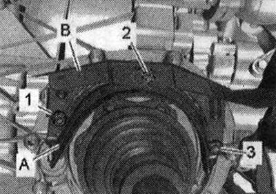
Unscrew bolts -1,2,3- and remove heat shield -A- for right drive shaft. Place the heat protection flaps -B- to one side. Unscrew the left and right articulated shafts from the gearbox flange shafts.
Remove cover -1- from bottom of gearbox -arrow-.
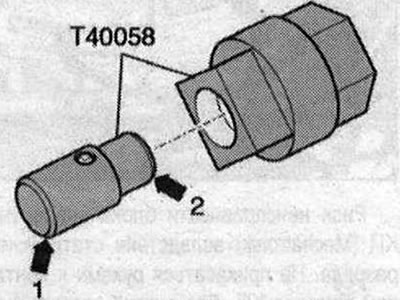
Insert guide pins of adapter -T40058- as shown below: large diameter -arrow 1 - faces engine. The small diameter -arrow 2- faces the adapter.
When loosening the driven disc bolts, use the adapter -T40058- to prevent the crankshaft from turning. During final rotation, turn the crankshaft only in the direction of engine rotation -arrow-.
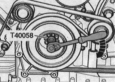
Unscrew the 6 bolts -arrow- of the torque converter; to do this, turn the crankshaft in increments of 60°in the direction of engine rotation.
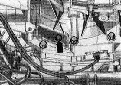
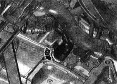
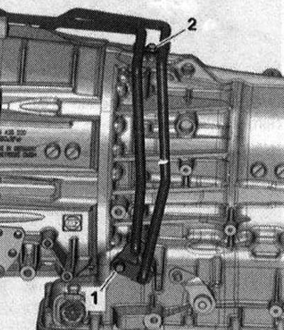
Unscrew bolt -arrow- for ATF lines. -Pos. 1,2 - do not take into account.
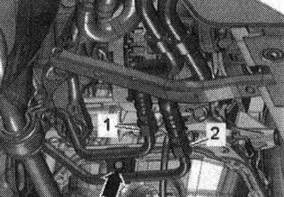
Place a rag under the disconnect point to catch the escaping ATF. Unscrew bolts -1- and -2-, disconnect ATF line -1- from gearbox and tie up at the top. Seal open lines and pipes with clean plugs from the engine plug set -VAS 6122-.
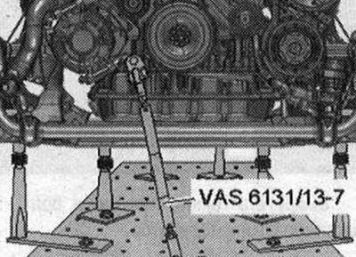
Prepare lifting table -VAS 6131 A- with Audi mounting kit -VAS 6131/10, additional kit -VAS 6131/13- and mounting bracket -VAS 6131/14- as follows: The remaining mounting elements remain unchanged. Screw the guide -VAS 6131/13-7-on the right side of the engine into the threaded hole as shown in the illustration. Secure the jig -VAS 6131 /13-7- to the lifting table with a torque of 20 Nm.
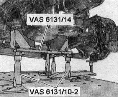
Remove bolts -1- and -2- from starter. Press the starter away from the gearbox and leave it in the installation position. Unscrew the remaining bolts -3...11- securing the engine to the gearbox. -Pos. A - ignore. Danger of leaking ATF oil pan. The mounting bracket -VAS 6131/14 must not be attached to the ATF oil pan. Install the guides from -VAS 6131/10- and the gearbox retainer -VAS 6131/14- on the front of the gearbox as shown in the illustration. Turn the right and left spindles upwards until the gearbox retainer -VAS 6131/14- fits snugly on the gearbox. Screw the support plates of the mounting elements with a torque of 20 Nm to the lift table -VAS6131 A-.
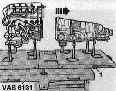
Unscrew the clamping bolts -1- from the side of the lift table -VAS 6131 A- and move the rear platform with the gearbox back -arrow-.
Visitor comments