
Tightening torques
Note. Tightening torques apply to lightly lubricated, oiled, phosphated or oxidized nuts and bolts. It is allowed to use additional lubricants, such as motor or transmission oils, except those containing graphite. Do not use degreased parts. The tightening torque tolerance is±15%.
Bolts and nuts
M6: 9 Nm, M7:15 Nm, M8:20 Nm, M10:40 Nm, M12:65 Nm.
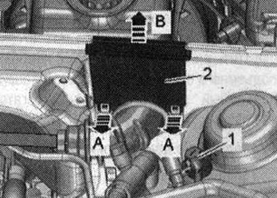
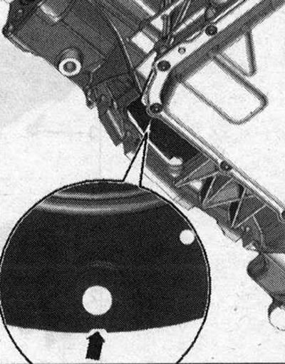
The ground bolt is to the body next to the shock absorber cup. Torque
Tighten the ground bolt -1 to a torque of 9 Nm.
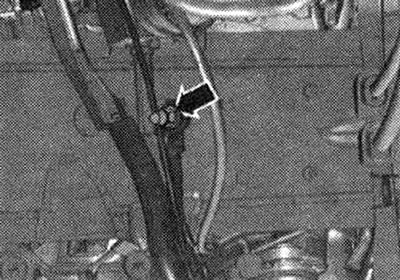
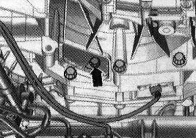
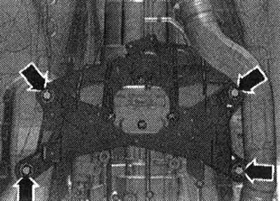
Ground wires to side members. Torque
Tighten nut -arrow- to 9 Nm.
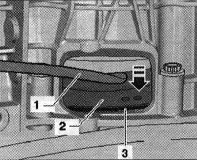
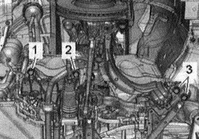
Drive shaft heat shield. Torque
Tighten bolts -1, 2, 3- to 23 Nm.
Engine for automatic transmission 0V6
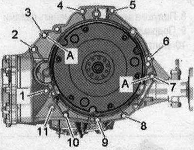
| Pos. | Bolt | Nm |
| 1 | M10x50 1) | 65 |
| 2...6 | М12x100 2) | 30 + 90° |
| 7 | M12x125 2) | 30 + 90° |
| 8,11 | M 10x60 2) | 15 + 90° |
| 9 | M10x75 2) | 15 + 90° |
| 10 | М10Х95 2) | 15 + 90° |
| A | Alignment sleeves |
- 1) Bolt strength class 10.9, steel bolt can be used repeatedly
- 2) Aluminum bolts can be used twice
Aluminum bolts -2...11- may not be used more than 2 times. Therefore, after using the bolts once, 2 notches should be made "X" -arrow-.
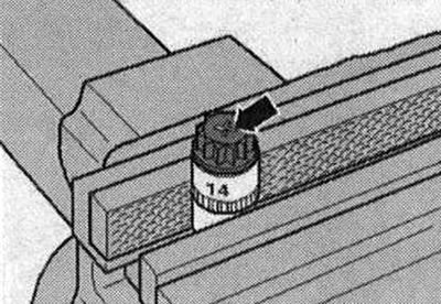
To avoid damaging the bolts, do not clamp them in a vice. Insert a 14 mm bolt into the head with an extension 112, the other end of which is secured in a hand vise (as shown in the picture). Bolts marked "X", must not be reused.
Note. Replace bolts that were overtightened. Replace self-locking nuts, lip seals, gaskets and seals. rings. On vehicles with a 0B6 automatic transmission, there may not be a needle bearing in the driven disk. Before installing the disc, make sure the needle bearing is installed. Press the needle bearing out of the driven disk. Secure all hose connections with hose clamps of the appropriate series. To ensure reliable fastening of the air hoses to the fittings, the threaded connections of already used clamps should be treated with a rust remover. During installation, all cable ties should be placed in the same places.
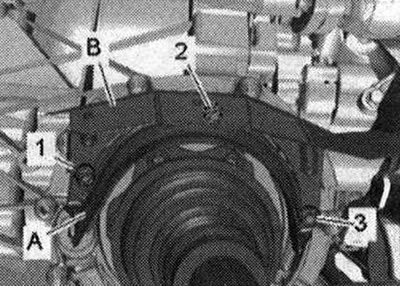
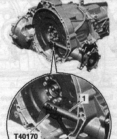
When installing the engine on the subframe, keep the ATF lines in the mounting position. Be sure to clean the threaded holes for fixing the power unit in the cylinder block before assembling the gearbox with a tap. Before securing the engine to the gearbox, do the following: rotate the torque converter so that the hole next to the notch -arrow- is visible in the opening under the gearbox housing, as shown in the figure.
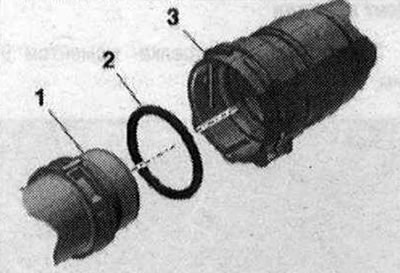
In order to find the notch, you need to turn the torque converter. Insert the transport lock
-T40170- from below into the gearbox housing and secure it to the shaft with flange -1-.
If necessary, check the possibility of reusing the aluminum engine mounting bolts on the gearbox and mark them.
Make sure that the installation bushings -A- are present for aligning the engine and gearbox in the cylinder block; if necessary, insert the missing bushings. Place the gearbox on the engine and tighten the bolts -1...11 -. Remove transport protection -T40170-. Install the engine mounts and engine mount. The next step is necessary to ensure that the torque converter rests evenly on the driven disk and does not warp. Lightly press the torque converter -2- using a pry bar -1- against the driven disc -3-, see -arrow direction-.
Secure the torque converter to the driven disc as follows: Use ring spanner 16 -VAG 1332/14- to tighten the bolts. Screw in the first bolt -arrow- by hand (2 Nm).
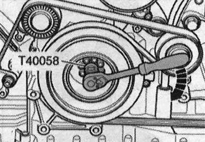
Insert guide pins of adapter -T40058- as follows: Large diameter -arrow 1 - faces engine. The small diameter -arrow 2- faces the adapter. Using adapter -T40058-, rotate the crankshaft 180°in the direction of engine rotation -arrow-.
In this crankshaft position, tighten the accessible bolt -arrow- to the specified torque.
Rotate the crankshaft 60°and tighten the remaining 5 bolts to the specified torque. Install the power steering hydraulic lines. Screw the left and right drive shafts to the axle shafts with gearbox flanges. Install the drive shaft heat shield. Install the exhaust manifold: left, right. Raise the power unit using the lifting table -VAS 6131 A-. Position the subframe and gearbox bracket according to the markings made on the side members during dismantling. Tighten the subframe bolts to the specified torque, but do not tighten them at an angle (tightening only after measuring the wheel alignment angles). If the subframe bolts are not completely tightened, the vehicle cannot be moved. Tighten the bolts -arrows- for the tunnel cross member.
Installation in reverse order: install ATF lines. Tighten the bolts securing the cardan joint to the crosspiece on the steering gear. Install the driveshaft. Install the selector cable. Install an additional muffler. Install the subframe extension, upper suspension arm, stabilizer, tighten the bolts securing the shock absorber strut to the support arm. Install the brake. caliper Install the engine control unit. Electrical connectors and wiring. Install wires, splitter 2 cells. 30 -TV22- and the engine switch box cover. compartment Install a stretcher. Install the filler neck of the washer fluid reservoir. Install the refrigerant lines. Follow the instructions after connecting the battery terminals. Risk of damage to control units due to overvoltage. Do not use a charger to start the engine! Install fuel discharge hose and air housing. filter. Install the cross members of the lock mounting beam. Add oil and check its level. Before starting the engine for the first time, fill hydraulic oil into the expansion tank. power steering reservoir. The power steering vane pump should not work "dry". Connect the coolant hose using a coupling. Fill with coolant.
Fill the air conditioning circuit. Install the front wheels and adjust the wheel alignment angles. Tighten the subframe bolts after checking the wheel alignment. Check ATF level. Install soundproofing screens and fender liners.
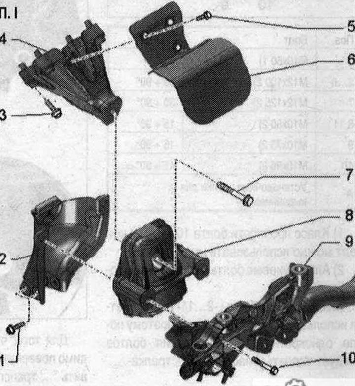
Engine mounting elements and gearbox installation. I 1. Bolt. 20 Nm; 2. Engine mount mounting plate. If the engine mount is defective, replace the mounting plate. Check the mounting plate on the opposite side and replace if necessary; 3. Bolt. 40 Nm; 4. Engine support; 5. Bolt. 10 Nm; 6. Thermal insulation; 7. Bolt. Replace. 90 Nm + additional rotation by 90°; 8. Engine mount. Replace in pairs; 9. Subframe; 10. Bolt. 55 Nm
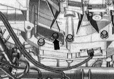
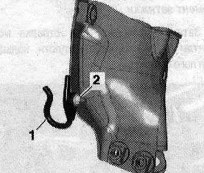
Hydraulic hose holder.
Torque
Tighten the washer -2- of the hydraulic hose holder -1- to a torque of 9 Nm.
Visitor comments