



Gasoline engine 3.2L car Audi Q5 (8R)

Engine number 3.2 l
The engine number will be visible only after removing the engine compartment cover. The engine number ("engine letter designation" and "serial number") is...
The engine number will be visible only after removing the engine compartment cover. The engine number ("engine letter designation" and "serial number") is...

Removal the engine
Note. The engine with gearbox and subframe is removed downwards with the radiator frame installed. For disposal or reuse, coolant should be drained into a...
Note. The engine with gearbox and subframe is removed downwards with the radiator frame installed. For disposal or reuse, coolant should be drained into a...

Engine disconnection
Disconnecting the engine and gearbox 0B6 The power unit is removed and installed on the lifting table "VAS 6131. A". Remove the plug connector "1" of the...
Disconnecting the engine and gearbox 0B6 The power unit is removed and installed on the lifting table "VAS 6131. A". Remove the plug connector "1" of the...

Engine installation
Tightening torques Note. Tightening torques apply to lightly lubricated, oiled, phosphated or oxidized nuts and bolts. The use of additional lubricants, such...
Tightening torques Note. Tightening torques apply to lightly lubricated, oiled, phosphated or oxidized nuts and bolts. The use of additional lubricants, such...

Cylinder block from the belt pulley side
Poly V-drive 1. Poly V-belt. Before removing, mark the direction of travel with chalk or a felt-tip pen. Do not bend. When installing, ensure the correct...
Poly V-drive 1. Poly V-belt. Before removing, mark the direction of travel with chalk or a felt-tip pen. Do not bend. When installing, ensure the correct...

Cylinder block from the gearbox side
Note: To perform installation work, it is necessary to secure the engine using the V6-FSI engine mount "VAS 6095/1" 5-on the bracket for the engine and gearbox...
Note: To perform installation work, it is necessary to secure the engine using the V6-FSI engine mount "VAS 6095/1" 5-on the bracket for the engine and gearbox...

Pistons and connecting rods
Pistons and connecting rods 1. Bolts. Replace. Lubricate the threads and mating surface with oil. 30 Nm + 90° turn; 2. Connecting rod cap. Mark for reassembly....
Pistons and connecting rods 1. Bolts. Replace. Lubricate the threads and mating surface with oil. 30 Nm + 90° turn; 2. Connecting rod cap. Mark for reassembly....

Overview of drive chain covers
Overview of drive chain covers. I 1/3/5/12/18/20. Bolt; 2. Crankshaft seal on the gearbox side. Replace; 4. Mounting sleeve. 2 pcs.; 6. Left cylinder head...
Overview of drive chain covers. I 1/3/5/12/18/20. Bolt; 2. Crankshaft seal on the gearbox side. Replace; 4. Mounting sleeve. 2 pcs.; 6. Left cylinder head...

Removal the lower cover of the drive chains
Gearbox removed. Disconnect battery. Remove driven disk. Remove protective covers of camshaft chains on left and right. Remove oil filter housing. Remove...
Gearbox removed. Disconnect battery. Remove driven disk. Remove protective covers of camshaft chains on left and right. Remove oil filter housing. Remove...

Camshaft chain drives
Left camshaft timing chain 1/2. Bolt. Replace. 80 Nm + 90° turn; 3. Exhaust camshaft phase shifter. Marking "Exhaust"; 4. Intake camshaft phase shifter....
Left camshaft timing chain 1/2. Bolt. Replace. 80 Nm + 90° turn; 3. Exhaust camshaft phase shifter. Marking "Exhaust"; 4. Intake camshaft phase shifter....

Removal the camshaft drive chains
Gearbox removed. Remove lower cover of timing chains. Remove chains from camshafts. Risk of failure due to reverse running of already used timing chain. For...
Gearbox removed. Remove lower cover of timing chains. Remove chains from camshafts. Risk of failure due to reverse running of already used timing chain. For...

Timing chain
Timing chain 1. Dampener bar; 2. Bolt. Replace. 10 Nm + 90° turn; 3. Bolt; 4. Axial locking washer for the drive sprocket; 5. Left drive chain sprocket; 6....
Timing chain 1. Dampener bar; 2. Bolt. Replace. 10 Nm + 90° turn; 3. Bolt; 4. Axial locking washer for the drive sprocket; 5. Left drive chain sprocket; 6....

Auxiliary drive chain
Auxiliary drive chain 1. Crankshaft; 2. Auxiliary drive chain. Before removing, mark the direction of travel with paint; 3. Oil pump chain drive sprocket....
Auxiliary drive chain 1. Crankshaft; 2. Auxiliary drive chain. Before removing, mark the direction of travel with paint; 3. Oil pump chain drive sprocket....

Balance shaft
Balance shaft 1. Balance shaft; 2. Bolt. 60 Nm. Use a 8 mm drill bit as a counter support to loosen and tighten; 3. Counterweight from the gearbox side. It is...
Balance shaft 1. Balance shaft; 2. Bolt. 60 Nm. Use a 8 mm drill bit as a counter support to loosen and tighten; 3. Counterweight from the gearbox side. It is...

Cylinder head
The figure shows the cylinder head of the 2nd row of cylinders (left). Cylinder head 1. Cylinder head seal. Installation position: the part number faces the...
The figure shows the cylinder head of the 2nd row of cylinders (left). Cylinder head 1. Cylinder head seal. Installation position: the part number faces the...

Removal the cylinder head
The engine is installed. The following describes the simultaneous removal of both cylinder heads. If you only need to remove one cylinder head, you can skip...
The engine is installed. The following describes the simultaneous removal of both cylinder heads. If you only need to remove one cylinder head, you can skip...

Compression check
Oil temperature not less than 30. Battery voltage minimum 12.5 V. Remove the rear engine cover -upper arrows-. Remove the brace. Unscrew the bolts "arrows"....
Oil temperature not less than 30. Battery voltage minimum 12.5 V. Remove the rear engine cover -upper arrows-. Remove the brace. Unscrew the bolts "arrows"....
Valve mechanism repair
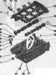
Caution! Risk of damage to valves and piston crowns after working on the valve train. Since the hydraulic valve lifters must be settled, do not start the...
Caution! Risk of damage to valves and piston crowns after working on the valve train. Since the hydraulic valve lifters must be settled, do not start the...

Lubrication system
Lower and upper parts of the oil pan, oil pump, engine oil radiator. I 1. Nut. 9 Nm; 2. Oil level and temperature sensor "G266"; 3. Sealing cuff. Replace; 4....
Lower and upper parts of the oil pan, oil pump, engine oil radiator. I 1. Nut. 9 Nm; 2. Oil level and temperature sensor "G266"; 3. Sealing cuff. Replace; 4....

Removal the oil filter housing
Remove the rear engine cover -upper arrows-. Remove the oil filter element. Pump out the oil using a device for pumping out oil from the oil filter housing....
Remove the rear engine cover -upper arrows-. Remove the oil filter element. Pump out the oil using a device for pumping out oil from the oil filter housing....

Cooling system
Caution. Risk of burns from hot steam and hot coolant. When the engine is warm, the cooling system is under excess pressure. To relieve excess pressure, place...
Caution. Risk of burns from hot steam and hot coolant. When the engine is warm, the cooling system is under excess pressure. To relieve excess pressure, place...

Draining and filling coolant
Open the expansion tank cap. Remove the front noise insulation "1". Install the tray for service cranes "VAS 6208" under the engine. Unscrew the threaded plug...
Open the expansion tank cap. Remove the front noise insulation "1". Install the tray for service cranes "VAS 6208" under the engine. Unscrew the threaded plug...
Cooling system pump, thermostat, fittings
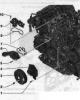
Cooling system pump, thermostat, fittings 1/5/10. Bolt. 9 Nm; 2. Bolt 20 Nm; 3. Coolant pump belt drive pulley; 4. Coolant pump with seal; 6. Connecting pipe...
Cooling system pump, thermostat, fittings 1/5/10. Bolt. 9 Nm; 2. Bolt 20 Nm; 3. Coolant pump belt drive pulley; 4. Coolant pump with seal; 6. Connecting pipe...

Radiator and radiator fan
Radiator and radiator fan 1. Used radiator fans "J293". Depending on the kit, separate or built into the radiator fan "V7"; 2. Bolt 4.5 Nm; 3/23. Bolt. 5 Nm;...
Radiator and radiator fan 1. Used radiator fans "J293". Depending on the kit, separate or built into the radiator fan "V7"; 2. Bolt 4.5 Nm; 3/23. Bolt. 5 Nm;...
Injection system
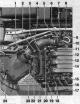
Installation location diagram Right side of the engine compartment 1. Lambda probe "G39". 55 Nm; 2. Valve 1 of the variable valve timing system of the exhaust...
Installation location diagram Right side of the engine compartment 1. Lambda probe "G39". 55 Nm; 2. Valve 1 of the variable valve timing system of the exhaust...

Air filter
Air filter 1. Hose clamp; 2. Air duct hose to the throttle control unit "J338". When installing, observe the marking (the arrow faces the bolt of the throttle...
Air filter 1. Hose clamp; 2. Air duct hose to the throttle control unit "J338". When installing, observe the marking (the arrow faces the bolt of the throttle...

Removal the lower part of the air filter housing
Remove the air duct hose from the air filter housing by unlocking the "arrow" clamps. Unscrew the "arrow" bolts from the upper part of the air filter housing...
Remove the air duct hose from the air filter housing by unlocking the "arrow" clamps. Unscrew the "arrow" bolts from the upper part of the air filter housing...

Upper part of the intake manifold
Upper part of the intake manifold 1. Vacuum hose; 2. Intake manifold sequential changeover valve "N156"; 3. Bolt for variable geometry intake manifold position...
Upper part of the intake manifold 1. Vacuum hose; 2. Intake manifold sequential changeover valve "N156"; 3. Bolt for variable geometry intake manifold position...

Lower part of the intake manifold with fuel rail
Lower part of the intake manifold with fuel rail 1. Lower part of the intake manifold; 2. Bushing; 3. Fuel pressure sensor "G247", 20 Nm; 4. Bracket; 5/7/13....
Lower part of the intake manifold with fuel rail 1. Lower part of the intake manifold; 2. Bushing; 3. Fuel pressure sensor "G247", 20 Nm; 4. Bracket; 5/7/13....

Removal the upper part of the intake manifold
Remove the front and rear engine casing. Release the hose line "1" to the activated carbon canister. Remove the vacuum hose "2" from the air duct hose branch....
Remove the front and rear engine casing. Release the hose line "1" to the activated carbon canister. Remove the vacuum hose "2" from the air duct hose branch....

High pressure pump
High pressure pump 1. The fuel metering valve "N₂90" cannot be removed from the high-pressure fuel pump; 2. Fuel pressure sensor of the low-pressure circuit...
High pressure pump 1. The fuel metering valve "N₂90" cannot be removed from the high-pressure fuel pump; 2. Fuel pressure sensor of the low-pressure circuit...

Removal injectors
Cut out a semicircle as shown in the picture. The semicircle allows the tool to be placed deeper on the nozzle, which provides a larger plane of contact for...
Cut out a semicircle as shown in the picture. The semicircle allows the tool to be placed deeper on the nozzle, which provides a larger plane of contact for...

Exhaust system
Muffler 1/13/21. Bolt. 23 Nm; 2. Suspension mount. Replace if damaged. Check pre-tension; 3. Middle muffler. At the factory it is installed as one part with...
Muffler 1/13/21. Bolt. 23 Nm; 2. Suspension mount. Replace if damaged. Check pre-tension; 3. Middle muffler. At the factory it is installed as one part with...

Exhaust manifold
Exhaust manifold 1. Nut. Replace. Lubricate with heat-resistant paste; 2. Heat shield bracket; 3. Exhaust manifold; 4. Gasket. Replace; 5. Thermal insulation...
Exhaust manifold 1. Nut. Replace. Lubricate with heat-resistant paste; 2. Heat shield bracket; 3. Exhaust manifold; 4. Gasket. Replace; 5. Thermal insulation...

Ignition system
Ignition system 1. Ignition coil connector 4-pin; 2. Bolt, 10 Nm; 3.3 pin plug connector; 4. Hall sensor: Hall sensor "G40" (cylinder bank 1); Hall sensor 3...
Ignition system 1. Ignition coil connector 4-pin; 2. Bolt, 10 Nm; 3.3 pin plug connector; 4. Hall sensor: Hall sensor "G40" (cylinder bank 1); Hall sensor 3...
This section is available on russian, bulgarian, belarusian, ukrainian, serbian, croatian, romanian, polish, slovak, hungarian
Share information:
- General information
- Operating instructions
- Maintenance
- Power unit
- Diesels 3.0 l (BUG, BUN, CAS)
- Diesels 3.0 l (CATA, CCMA)
- Diesels 3.0 l (CJGA/CJGC)
- Diesels 4.2 l (BTR, CCFA/CCFC)
- Cooling system
- Fuel and exhaust system
- Engine management system
- Starting and charging
- Transmission
- Automatic gearbox
- Drive shafts
- Chassis
- Brake system
- Front suspension
- Rear suspension
- Steering system
- Body
- Air conditioner
- Exterior
- Interior
- Electrical equipment
- Equipment and devices
- Electrical circuits
- General information
- User manual
- Power unit
- Petrol engine 2.0 l
- Petrol engine 3.2 l
- Fuel system (petrol)
- Diesel 2.0 liter (CA)
- Diesel 2.0 liter (CG/CJ/CM)
- Diesel engine 3.0 l
- Fuel system (diesel)
- Transmission
- Manual gearbox 0B1
- Manual gearbox 0B2
- Automatic gearbox 0B5
- Automatic gearbox 0B6
- Chassis
- Front suspension
- Rear suspension
- Brake system
- Steering
- Body
- Exterior
- Interior
- Doors, locks and windows
- Safety system
- Ventilation and heating
- Electrical equipment
- Power devices
- Equipment and devices
- Lighting and alarm
- Audio system
- Electrical circuits