
Note. The engine with gearbox and subframe is removed downwards with the radiator frame installed. For disposal or reuse, coolant should be drained into a clean container. When reassembling, install all binders in the places where they were originally installed.
Attention! There is a danger of the vehicle tipping over when the engine is removed. Protect the vehicle; to do this, the luggage compartment must be empty. Risk of injury from fuel under very high pressure. Before depressurizing the injection system, it is necessary to reduce the fuel pressure to the residual pressure.
Relieve fuel pressure in the high pressure sector.
Carefully! Risk of damage to electronic components. Follow the instructions when disconnecting the battery terminals.
Move the front wheels to a straight ahead position.
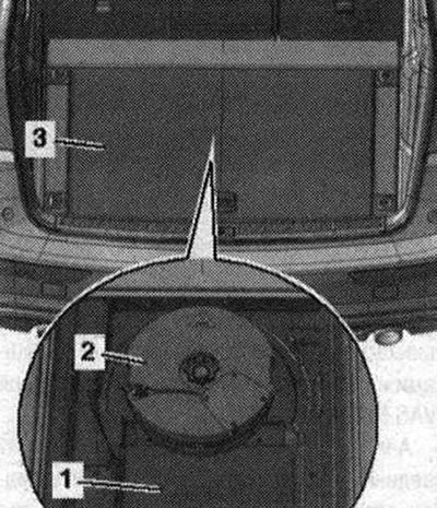
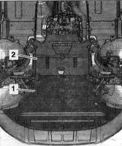
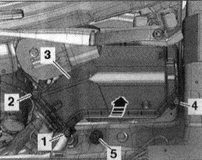
Note. In order to rotate the driveshaft to remove it, you must disengage the electromechanical parking brake before disconnecting the battery terminals. Turn off the ignition and remove the ignition key. Remove trunk tray -3-. If present, remove Bassbox -2-. Unscrew the floor covering -1- above the cover.
Engine characteristics
| Letter designations | CALB |
| Working volume (l) | 3,197 |
| Power (kW at rpm) | 199/5000 |
| Torque (Nm at rpm) | 330/3000 |
| Cylinder diameter (mm) | 85,5 |
| Piston stroke (mm) | 92,8 |
| Compression | 12,5 |
| Minimum octane number | 95 1) |
| Injection/ignition system | Simos |
| Cylinder operating order | 14-3-6-2-5 |
| Anti-knock regulation | 2 sensors |
| Lambda regulation | 4 lambda probes |
| Timing phase adjustment | Inlet and outlet |
| Changing the intake manifold geometry | provided |
| Secondary air supply system | provided |
| Number of valves per cylinder | 4 |
1) Unleaded gasoline fuel with 91 octane number is allowed, but this reduces engine power
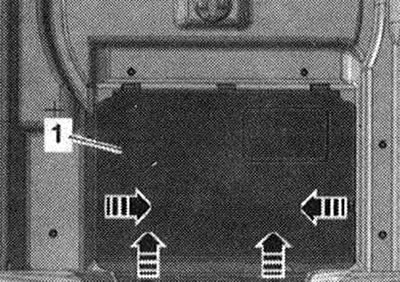
Unlock fastenings -arrows- and install cover -1 -.
Remove the cover -1- over the negative terminal of the battery. Disconnect earth cable -arrow- from battery terminal. Empty the air conditioning circuit. Drain the power steering hydraulic oil using an oil drain tool from the reservoir.
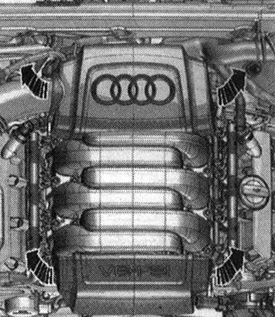
Remove the motor covers. compartment
Attention. Risk of burns from hot steam and hot coolant. When the engine is warm, the cooling system is under excess pressure. To relieve excess pressure, cover the expansion cap. coolant reservoir with a rag and carefully open it.
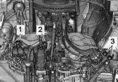
Open the extension cover. tank. Remove the front wheels: right and left. Remove the front right and left fender liner. Remove noise insulation panels -1- and -2-.
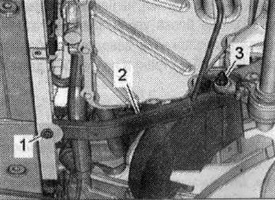
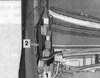
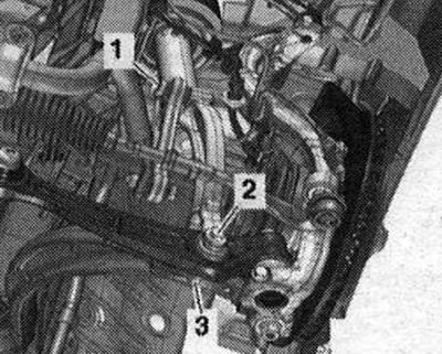
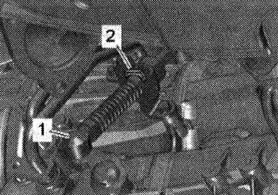
Place service tap tray -VAS 6208- under the engine. Unscrew the drain plug -1 - and drain the coolant. Remove the coolant hose -2- from the radiator by pressing the mounting bracket.
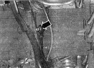
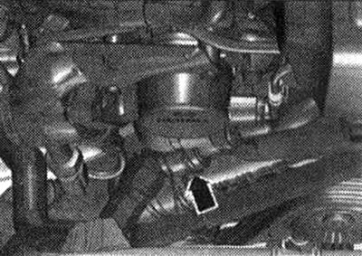
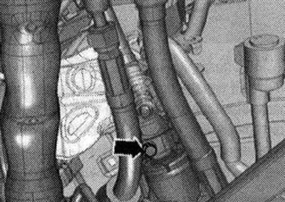
Remove the coolant hose from the engine oil cooler by loosening the hose clamp -arrow- and drain the remaining coolant.
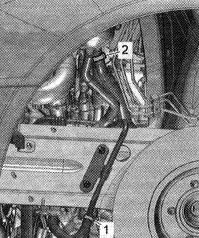
Install a device for pumping out and collecting oil under the disconnection point. Disconnect supply hose -2- and return hose -1 - for power steering hydraulic oil in left front wheel housing and release. Seal open lines and pipes with clean plugs from the engine plug set -VAS 6122-.
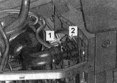
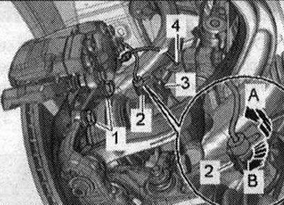
Install a device for pumping out and collecting oil under the disconnection point. Mark the installation position of the ATF lines -1 - and -2- for reinstallation and disconnect the ATF lines.
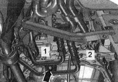
-Arrow- ignore. Seal open lines and pipes with clean plugs from the engine plug set -VAS6122-.
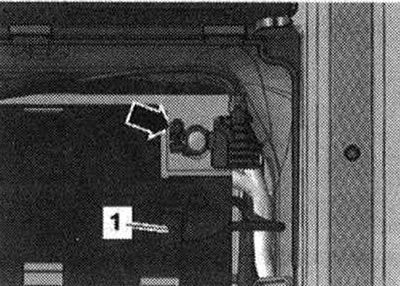
Vehicles with coolant circulation pump -V50-: Disconnect electrical connection. connector -1-. Place service tap tray -VAS 6208- under the engine. Disconnect coolant hose from coolant circulation pump -V50- -arrow right-.
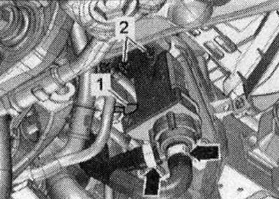
-Pos. The 2nd and -left arrows should not be taken into account.
All
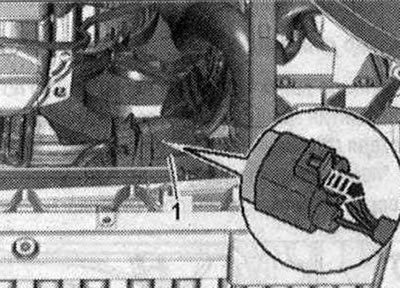
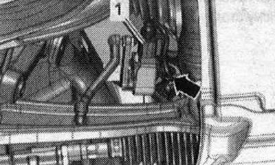
Disconnect el. Plug connection -1- of the radiator fan; to do this, push the locking pin back -arrow- and press the lock downwards. Release the wiring harness.
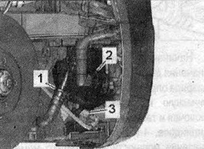
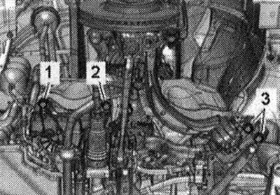
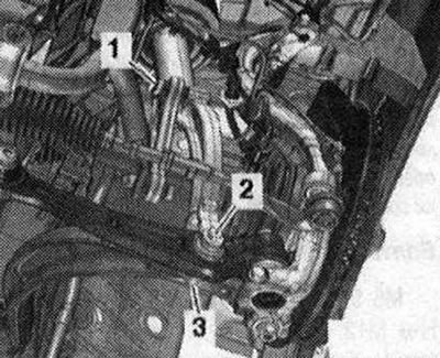
Disconnect electrical connector -3- from secondary air pump motor -V101- and unplug electrical wiring. -Pos. 1, 2 - do not take into account.
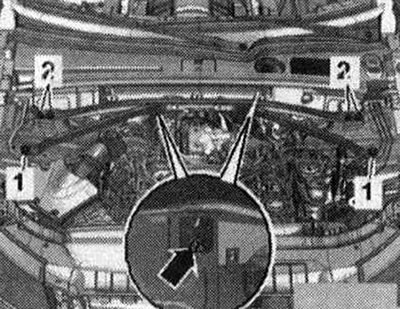
Unscrew the left and right bolts -1- and the nut -3-, remove the radiator frame cross members -2-.
Unscrew the nut -arrow- on the right side member and release the ground cables.
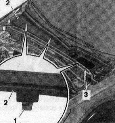
Unscrew the bolts -1-, as well as the nuts -2- and -3-, and remove the extension.
Remove gasket -3-. Release the mounting clips -1- from the mountings and remove the plenum chamber cover -2-.
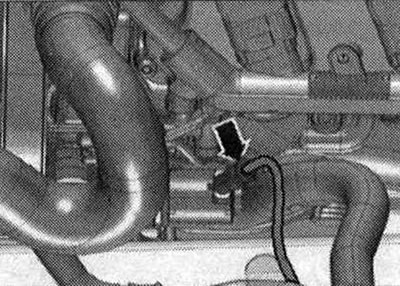
Disconnect vacuum hose -arrow- to fuel diagnostic pump. systems -V144-.
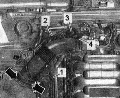
Remove the vacuum pipe -2- from the front wall; to do this, remove the vacuum hose -1- on the reverse side. Release fuel. line and the line going to the activated carbon absorber on the air tube. -Pos. 3.4-ignore.
Remove air duct -arrow-.
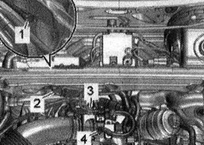
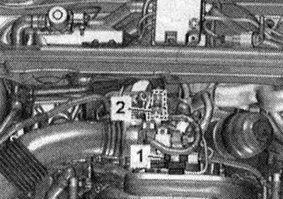
Remove the vacuum hose -3- from the fitting on the air line. Remove the air pipe by loosening the clamp -4- and unlocking the locking clips -arrows-. Release fuel. hose -1- from the air pipe. -Pos. 2- do not take into account.
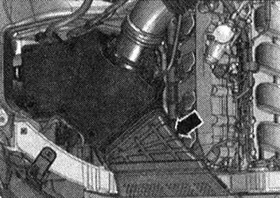
Remove the air housing. filter and on the reverse side the secondary supply hose -arrow-. air by pressing the locking tabs.
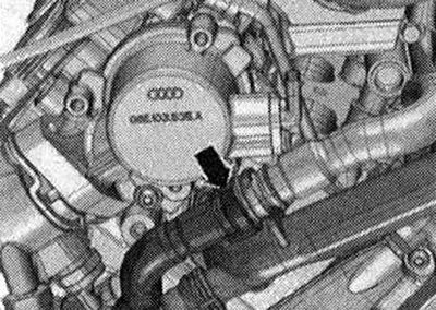
Unscrew the fuel supply. hose from the high-pressure pump -arrow- and place to one side.
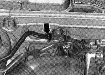
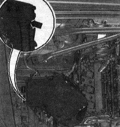
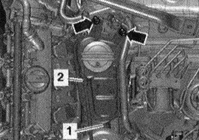
Disconnect and release vacuum hose -1-. Remove the coolant hose -2- from the upper coolant pipe; to do this, press the mounting bracket.
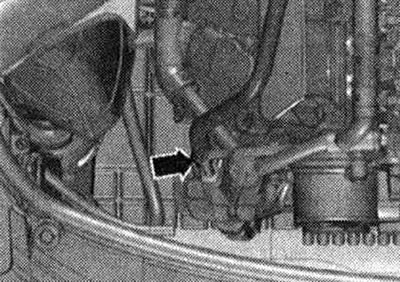
Remove the hose from the bracket -arrow-second. air forward by pressing the locking tabs.
Vehicles without coolant circulation pump -V50-: Remove the front right coolant hose -arrow- from the coolant pipe; to do this, press the retaining clip.
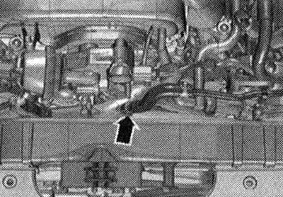
Remove the coolant hose from the front coolant pipe by pressing out the retaining clip -arrow-.
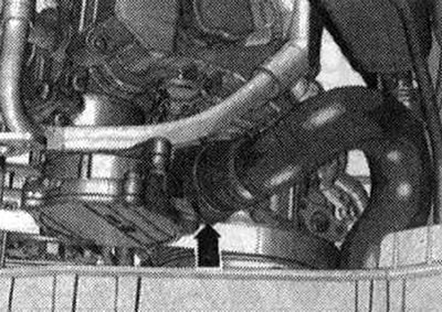
Remove coolant hose by loosening hose clamp -arrow-.
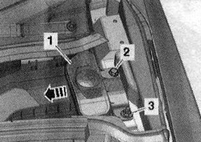
Remove coolant hose -2- from extension. tank. Unscrew the bolts -arrows-, disconnect the electrical connector for the low coolant level warning switch -F66- and place the extension to one side. coolant reservoir with connected coolant hose -1-.
If present, disconnect the electrical connection. connector -arrow- from the power steering pump.
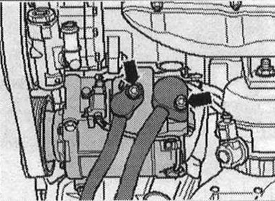
Slightly press down the hydraulic oil hose. Unscrew the bolts -arrows- and remove the coolant lines from the compressor. Seal open lines and pipes with clean plugs from the engine plug set -VAS 6122-.
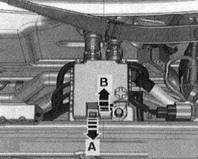
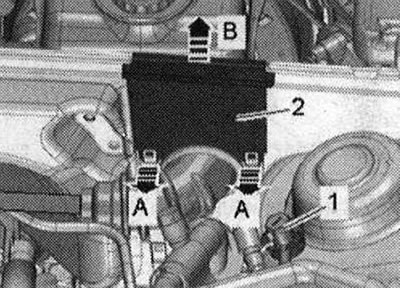
Unlock lock -arrow A- and open cover -arrow B-.
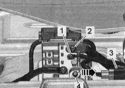
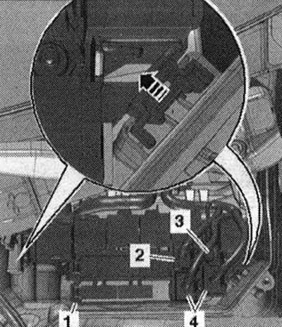
Unscrew nuts -1- and -2- for electrical wiring. Remove email plug connection -3- from the holder and disconnect it. Unscrew bolt -4- and remove splitter 2 cells. 30 -TV22-with extension -arrow-.
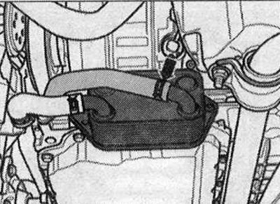
Remove the foam block -1 - towards the top. -Pos. 2- ignore
Unlock the clamps from the wheel arch using a 5.5-pos. spanner. 1 - and remove the cable gland -2- upwards. Release the wiring harness -3- going to the alternator and starter using the release lever -80-200-.
Open the wiring duct -1-, to do this, release the lock -arrow- and release the wiring harness.
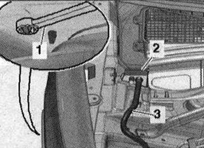
Unscrew nut -3- and bolt -2-. Remove the filler neck -1- with the filler tube from the washer fluid reservoir by guiding it through the body opening -arrow-.
Unscrew bolts -1,2,4- and remove cover -3- of the engine switching unit. compartment Unscrew the nut -5- and release the ground wire.
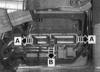
Unlock the latches -arrows A- and remove the engine control unit -arrow B-.
Disconnect (in the presence of) plug connector -2-. Disconnect plug connectors -4- and unscrew electrical wiring -3-. Unlock the latches -arrow- and remove the fuse block. B -SB- -pos. 1 -. Remove and release the engine wiring harness secured in the connection box.
Unlock latches -arrows A- and remove cable guide -2- upwards -arrow B-. Unscrew the ground bolt -1- and free the wiring harness. Place the wiring harness on the engine and secure the engine control unit from falling out.
Disconnect the connector on the left and right of the front speed sensors -arrow-.
If present, disconnect the electrical connection. connectors -1- of the front left vehicle level sensor -G78- and the front right vehicle level sensor -G289- and release the electrical connection. cable -arrow-.
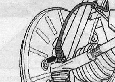
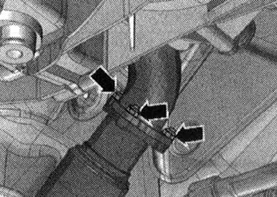
Disconnect the connector -2- from the bracket by pulling the locking pin backwards -arrow A- and turning the connector -in the direction of arrow B- approx. at 90°. Release el. wire -3- and brake hose -4- on the bracket. Unscrew the bolts -1- and hang the brake with wire. a caliper with a connected brake drive turbo line on the wheel well.
Risk of damage to brake cylinder pistons. Do not press the brake pedal with the brake caliper removed. Unscrew the nut -2- and remove the bolt -1-. Remove the upper suspension arm from the wheel bearing housing in an upward direction -arrows-. Repeat the entire process of performing work on the other side of the vehicle.
Unscrew the bolt -1 - of the stabilizer on the left and right. Unscrew nut -3- on left and right.
Bolt -2- will be removed later. Unscrew the nut -1- securing the hydraulic line of the power steering.
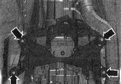
Risk of damage to chassis components. If the engine mounting elements, steering gear or subframe crosspiece are installed improperly, the vehicle must not be placed on wheels. It is prohibited to support the vehicle by the subframe or subframe crosspiece (for example, a jack, etc.)! Unscrew the bolts -arrows- and remove the subframe extension.
Risk of damage to the Airbag coil spring contact. Disconnect the cardan joint with the cross from the steering mechanism only in the position of the front wheels for straight-line movement. Do not change the position of the steering wheel or the position of the steering gear. Unscrew the bolt -arrow- from the cardan joint with the crosspiece. Press the cardan joint with the cross from the steering mechanism and move the joint up until it stops.
Unscrew nuts -arrows- on front left muffler.
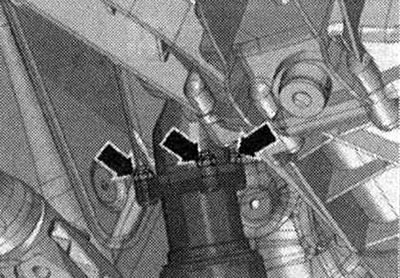
Unscrew nuts -arrows- on front right muffler.
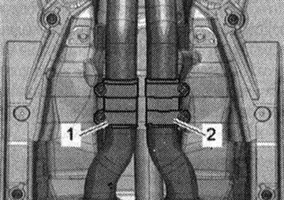
Risk of damage to the disconnecting components in the front silencers. Do not bend the release components in the front mufflers by more than 10°. Loosen and push back clamps -1 - and -2-, remove the left and right front mufflers.
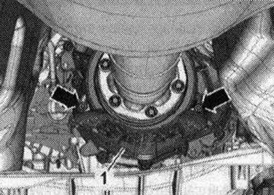
If present, unscrew the bolts -arrows- and remove the heat shield -1 - for the propeller shaft.
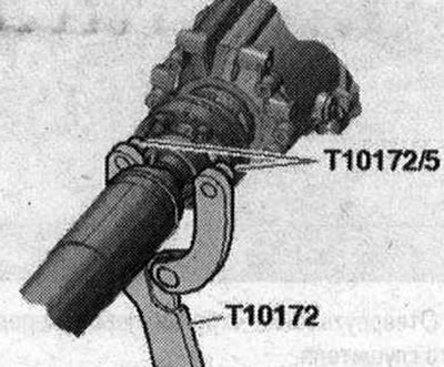
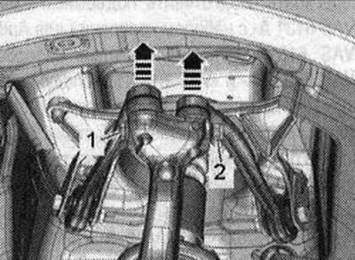
Unscrew the bolts securing the propeller shaft to the gearbox; to do this, hold the propeller shaft against turning with the support -T10172-c -T10172/5-. Move the driveshaft to the rear final drive housing; CV joints are movable in the axial direction. Tie the driveshaft to the side.
Press the ball joint -1- of the gearbox selector cable using lever -80-200- from the gearshift lever. Remove the locking bracket -2- and disconnect the gearbox selector cable from the gearbox.
The gear selector cable must not be bent or bent. Prepare the lift table -VAS 6131 A- with mounting set for Audi -VAS 6131/10-, additional set -VAS 6131/11- and -VAS 6131/13- as follows: First screw the fastening elements onto the lift table by hand. Install the lifting table for the units horizontally. Monitor the level (peephole) on the reception table. Place a lifting table under the power unit. Do not unscrew the subframe mounting bolts -2- and -3-. Unscrew the subframe bolt -1- on the left and right.
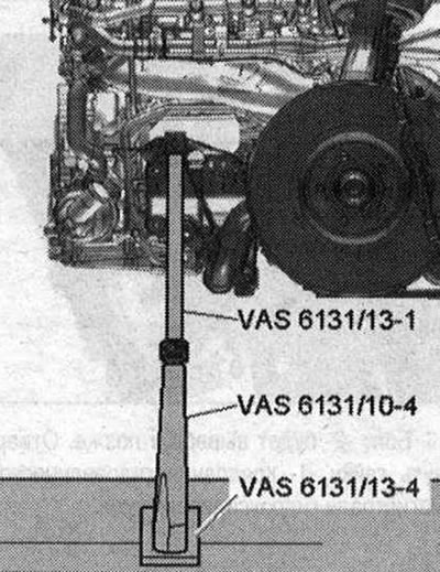
Install guides from -VAS 6131/10- and -VAS 6131/13- on the left and right of the front section of the subframe as shown in the illustration.
Make sure that the lead screws are completely screwed in.
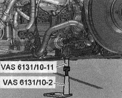
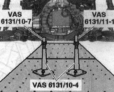
Install conductors from -VAS 6131/10 - rear left and right on the front threaded connections of the subframe extension, as shown in the illustration.
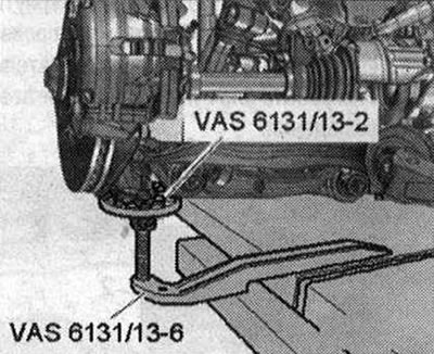
Install the jigs from -VAS 6131/13-left and right onto the lower part of the wheel bearing housing as shown in the illustration.
Install the guides from -VAS 6131/10- and -VAS 6131/11- at the rear left and right onto the tunnel cross member as shown in the illustration. Unscrew all the lead screws of the fastening elements upwards until all the mounting lugs fit into the fastening points. Screw the support plates of the mounting elements with a torque of 20 Nm to the lift table -VAS 6131 A-.
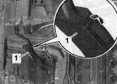
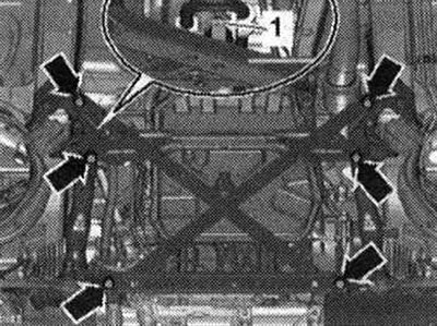
Mark the installation position of the subframe and tunnel cross member on the side members with a felt-tip pen. Unscrew the subframe bolts -2- and -3- crosswise in several stages. Bolt -1- is already unscrewed. Unscrew the bolts -arrows- for the tunnel cross member.
Unscrew bolt -2- on left and right. The nut -1- and bolt -3- have already been removed.
Risk of damage to hose and cable connections as well as motor. compartment Make sure that all hose and wire connections between the engine, transmission, subframe and body are disconnected. When lowering, carefully remove the power unit with subframe from the engine. compartment Lower the power unit using the lifting table -VAS 6131 A-. Pull the lift table with the power unit out from under the vehicle.
Visitor comments