



Diesel engine 2.0L (CG/CJ/CM) vehicle Audi Q5 (8R)

Engine characteristics
Engine characteristics Letter designations CGLA CGLB CGLB Working volume, l 1,968 1,968 1,968 Power, kW at rpm 120/4200 125/4200 125/4200 Torque, Nm at rpm...
Engine characteristics Letter designations CGLA CGLB CGLB Working volume, l 1,968 1,968 1,968 Power, kW at rpm 120/4200 125/4200 125/4200 Torque, Nm at rpm...

Engine number
Engine number ("engine letter designations" and "serial number") "arrow" is located on the left in the direction of travel at the junction of the engine and...
Engine number ("engine letter designations" and "serial number") "arrow" is located on the left in the direction of travel at the junction of the engine and...

Removal the engine
Caution! When installing a new, incomplete engine, it is essential to tighten the clamping brackets of the injection modules to the specified tightening torque...
Caution! When installing a new, incomplete engine, it is essential to tighten the clamping brackets of the injection modules to the specified tightening torque...

Engine installation
Tightening torques (Nm) Note: Tightening torques apply to lightly greased, oiled, phosphated or oxidised nuts and bolts. The use of additional lubricants, such...
Tightening torques (Nm) Note: Tightening torques apply to lightly greased, oiled, phosphated or oxidised nuts and bolts. The use of additional lubricants, such...

Disassembly and assembly of the engine
Sealing flange on the belt pulley side 1/7. Bolt; 2. Crankshaft timing belt pulley: There should be no oil on the mating surfaces between the timing belt...
Sealing flange on the belt pulley side 1/7. Bolt; 2. Crankshaft timing belt pulley: There should be no oil on the mating surfaces between the timing belt...

Removal the timing belt
Turn the tensioner clockwise "arrow", remove the poly V-belt from the generator pulley and remove the load from the tensioner. Remove the poly V-belt. "T40098"...
Turn the tensioner clockwise "arrow", remove the poly V-belt from the generator pulley and remove the load from the tensioner. Remove the poly V-belt. "T40098"...

Installation (adjustment of timing phases)
The engine must be cold to perform adjustment work on the toothed belts. Risk of damage to valves and piston bottoms. When turning the camshaft, not one piston...
The engine must be cold to perform adjustment work on the toothed belts. Risk of damage to valves and piston bottoms. When turning the camshaft, not one piston...

Checking the timing phases
Risk of damage due to the toothed belt jumping. Turn the crankshaft only in the direction of engine rotation. Turn the crankshaft by the toothed belt bolt 2...
Risk of damage due to the toothed belt jumping. Turn the crankshaft only in the direction of engine rotation. Turn the crankshaft by the toothed belt bolt 2...

Timing phase correction
If the camshaft hub cannot be locked, remove the crankshaft stopper "T10050" so that the journal opens access to the hole. Turn the crankshaft against the...
If the camshaft hub cannot be locked, remove the crankshaft stopper "T10050" so that the journal opens access to the hole. Turn the crankshaft against the...

Cylinder head
Cylinder head cover Caution! When installing a new, incomplete engine, it is essential to tighten the clamping brackets of the injection modules to the...
Cylinder head cover Caution! When installing a new, incomplete engine, it is essential to tighten the clamping brackets of the injection modules to the...

Removal the cylinder head cover
Remove the injection system unit. Remove the fuel distributor. Release the clamps "arrows", remove the protective cover of the toothed belt. Disconnect the...
Remove the injection system unit. Remove the fuel distributor. Release the clamps "arrows", remove the protective cover of the toothed belt. Disconnect the...

Cylinder head — Cylinder block head
Cylinder head 1. Cylinder head seal: replace; after replacement, replace the coolant and oil; 2. Bolt: insert with thread varnish; 10 Nm; 3. Hall sensor "G40":...
Cylinder head 1. Cylinder head seal: replace; after replacement, replace the coolant and oil; 2. Bolt: insert with thread varnish; 10 Nm; 3. Hall sensor "G40":...

Removal the cylinder head
Remove the front wall of the water drainage box. Remove the air filter housing. Remove the toothed belt. Remove the left upper coolant pipe. Disconnect the...
Remove the front wall of the water drainage box. Remove the air filter housing. Remove the toothed belt. Remove the left upper coolant pipe. Disconnect the...
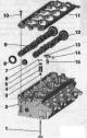
Valve mechanism
Valve mechanism 1. Valve: cannot be processed, only lapping is allowed; mark the mounting position for reinstallation; 2. Cylinder head; 3. Valve stem seal; 4....
Valve mechanism 1. Valve: cannot be processed, only lapping is allowed; mark the mounting position for reinstallation; 2. Cylinder head; 3. Valve stem seal; 4....

Removal camshafts
The cylinder head is installed. Remove the engine casing "arrows". Remove the air filter housing. Disconnect the engine crankcase ventilation hose "2" by...
The cylinder head is installed. Remove the engine casing "arrows". Remove the air filter housing. Disconnect the engine crankcase ventilation hose "2" by...
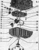
Oil pan, oil pump, balance shaft block
Oil pan, oil pump, balance shaft block I 1. Sealing cuff: replace; 2. Oil drain plug: 30 Nm; 3. Oil pan 4/21/23. Bolt: 9 N·m; 5. Suction pipe: if dirty, clean...
Oil pan, oil pump, balance shaft block I 1. Sealing cuff: replace; 2. Oil drain plug: 30 Nm; 3. Oil pan 4/21/23. Bolt: 9 N·m; 5. Suction pipe: if dirty, clean...

Removal the oil pan
Drain the oil. Remove the subframe. Unscrew the "arrow" nut on the right side member and release the ground wires. Disconnect the electrical plug connection...
Drain the oil. Remove the subframe. Unscrew the "arrow" nut on the right side member and release the ground wires. Disconnect the electrical plug connection...

Removal the oil pump
Remove the oil pan. Unscrew the bolt "arrow" and remove the suction pipe from the oil pump. Remove the retaining ring "1" using retaining ring pliers. Remove...
Remove the oil pan. Unscrew the bolt "arrow" and remove the suction pipe from the oil pump. Remove the retaining ring "1" using retaining ring pliers. Remove...

Removal the balance shaft module
Remove the dipstick. Remove the oil pan. Remove the cover from the vibration damper. Turn the crankshaft using the bent wrench "1" on the vibration damper in...
Remove the dipstick. Remove the oil pan. Remove the cover from the vibration damper. Turn the crankshaft using the bent wrench "1" on the vibration damper in...

Installing a new balance shaft module
Fix the camshaft using the locking pin of the direct injection pump of the diesel engine "3359". The cylindrical gear drive of the balance shaft module must be...
Fix the camshaft using the locking pin of the direct injection pump of the diesel engine "3359". The cylindrical gear drive of the balance shaft module must be...
Installation of a previously used balance shaft unit
Fix the camshaft using the locking pin of the direct injection pump of the diesel engine "3359". When installing the old balance shaft module, provided that...
Fix the camshaft using the locking pin of the direct injection pump of the diesel engine "3359". When installing the old balance shaft module, provided that...
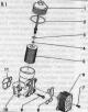
Oil filter bracket and oil cooler
Oil filter bracket and oil cooler. I 1. Cover: 25 Nm; 2:4. O-ring: replace; 5. Oil filter element: follow instructions; 6. Oil radiator: follow the...
Oil filter bracket and oil cooler. I 1. Cover: 25 Nm; 2:4. O-ring: replace; 5. Oil filter element: follow instructions; 6. Oil radiator: follow the...

Removal the oil pressure sensor
Removal the oil pressure sensor -F1 Remove the air filter housing. Remove the stretch. Unscrew bolts "2" and "3", remove engine eye "1". Connect the electrical...
Removal the oil pressure sensor -F1 Remove the air filter housing. Remove the stretch. Unscrew bolts "2" and "3", remove engine eye "1". Connect the electrical...

Cooling system
Coolant hose connection diagram Note: Blue = large coolant circuit. Red = small coolant circuit. Brown = heating circuit. Orange = cooling circuit for exhaust...
Coolant hose connection diagram Note: Blue = large coolant circuit. Red = small coolant circuit. Brown = heating circuit. Orange = cooling circuit for exhaust...

Supercharging system
Caution! Risk of engine malfunction. When laying vacuum hoses, avoid bending, twisting or pinching them. Vacuum hose connection diagram 1. Electromagnetic...
Caution! Risk of engine malfunction. When laying vacuum hoses, avoid bending, twisting or pinching them. Vacuum hose connection diagram 1. Electromagnetic...

Turbocharger — removal, installation
Turbocharger 1. Air duct hose; 2. Pulsation damper; 3. Return oil line; 4/16/25. Bolt: 9 Nm; 5. Gasket: replace; 6. Threaded nipple: 40 Nm; 7. Gasket: replace;...
Turbocharger 1. Air duct hose; 2. Pulsation damper; 3. Return oil line; 4/16/25. Bolt: 9 Nm; 5. Gasket: replace; 6. Threaded nipple: 40 Nm; 7. Gasket: replace;...

Injection system
Installation location of the injection system. I 1. Air flow meter "G70"; 2. Air filter bypass valve "N₂75": domestic market version; 3. Plug connectors: for...
Installation location of the injection system. I 1. Air flow meter "G70"; 2. Air filter bypass valve "N₂75": domestic market version; 3. Plug connectors: for...

Parts and units of the fuel system (general diagram)
Caution! Risk of malfunction due to contamination. To avoid dry running of the high-pressure fuel pump (very tight tolerances) and in order to quickly start...
Caution! Risk of malfunction due to contamination. To avoid dry running of the high-pressure fuel pump (very tight tolerances) and in order to quickly start...

Intake manifold parts and components
Intake manifold parts and components 1. Guide tube: for oil dipstick; 2. Sealing cuff: replace; 3. Gasket: replace; 4. Bolt: 8 Nm; 5. Return fuel line: the...
Intake manifold parts and components 1. Guide tube: for oil dipstick; 2. Sealing cuff: replace; 3. Gasket: replace; 4. Bolt: 8 Nm; 5. Return fuel line: the...

Removal the Throttle Control Module
Removal the Throttle Control Module "J338" Remove the engine casing. Loosen the hose clamp "arrow" and remove the air duct hose downwards. Disconnect the...
Removal the Throttle Control Module "J338" Remove the engine casing. Loosen the hose clamp "arrow" and remove the air duct hose downwards. Disconnect the...

Removal the intake manifold
Risk of malfunction due to contamination. Remove the engine casing. Disconnect the electrical plug connections of the glow plugs. Unscrew bolt "2" and union...
Risk of malfunction due to contamination. Remove the engine casing. Disconnect the electrical plug connections of the glow plugs. Unscrew bolt "2" and union...

Parts and units of high pressure pump
Parts and units of high pressure pump 1. Holder of additional units; 2. Bolt: 2 pcs.; replace; 20 Nm + 180°; 3. Hub: use the counter support "T10051" to loosen...
Parts and units of high pressure pump 1. Holder of additional units; 2. Bolt: 2 pcs.; replace; 20 Nm + 180°; 3. Hub: use the counter support "T10051" to loosen...

Injection nozzles
Caution! When installing a new engine, after installing the high-pressure lines, it is necessary to tighten the clamping brackets of the injectors to the...
Caution! When installing a new engine, after installing the high-pressure lines, it is necessary to tighten the clamping brackets of the injectors to the...

Removal injectors
Remove the engine cover. Caution! Mark the injectors to the cylinders. Re-installation is only permitted on the same cylinder. When working on the injection...
Remove the engine cover. Caution! Mark the injectors to the cylinders. Re-installation is only permitted on the same cylinder. When working on the injection...

Removal the diesel particulate filter
Remove the air filter housing. Remove the right front wheel. Remove the exhaust pipe. Remove lambda probe "G39" "pos. 1". Remove exhaust gas temperature sensor...
Remove the air filter housing. Remove the right front wheel. Remove the exhaust pipe. Remove lambda probe "G39" "pos. 1". Remove exhaust gas temperature sensor...

Exhaust gas temperature sensor
Exhaust gas temperature sensor 1. Middle muffler; 2. Nut; 3. NOx sensor 2 "G687"; 4. Sensor 4 of temperature of the exhaust gas "G648": the thread of the...
Exhaust gas temperature sensor 1. Middle muffler; 2. Nut; 3. NOx sensor 2 "G687"; 4. Sensor 4 of temperature of the exhaust gas "G648": the thread of the...

EGR system installation overview
EGR system installation overview 1. Gasket: replace; 2/4/6/10. Bolt: 9 Nm; 3. EGR pipe; 5. Gasket: replace; 7. Coolant hose; 8. Radiator of the exhaust gas...
EGR system installation overview 1. Gasket: replace; 2/4/6/10. Bolt: 9 Nm; 3. EGR pipe; 5. Gasket: replace; 7. Coolant hose; 8. Radiator of the exhaust gas...

Removal the EGR radiator
Remove the engine casing "arrows". Remove the air filter housing. Remove the stretcher. Drain the coolant. Disconnect the crankcase ventilation hose "2" by...
Remove the engine casing "arrows". Remove the air filter housing. Remove the stretcher. Drain the coolant. Disconnect the crankcase ventilation hose "2" by...
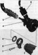
Nozzle for reducing agent «N474»
Nozzle for reducing agent "N474" 1. Bolt: 5 Nm; 2. Fastening clamp; 3. Gasket: replace; 4. Nozzle for reducing agent "N474"; 5. Hose: for the restorer; to...
Nozzle for reducing agent "N474" 1. Bolt: 5 Nm; 2. Fastening clamp; 3. Gasket: replace; 4. Nozzle for reducing agent "N474"; 5. Hose: for the restorer; to...

Recovering agent tank with attached components
Installation location: at the height of the rear seat, on the left under the bottom. Recovering agent tank with attached components 1. Bolt: 4.2 Nm; 2. Rear...
Installation location: at the height of the rear seat, on the left under the bottom. Recovering agent tank with attached components 1. Bolt: 4.2 Nm; 2. Rear...

Recovery pump «V437»
Pump of the reducing agent "V437" 1. Nozzle; 2. Bushing; 3. Bolt: 5 Nm; 4. Fuel supply line: with heater; 5. Electrical plug connection; 6. Pump for feeding...
Pump of the reducing agent "V437" 1. Nozzle; 2. Bushing; 3. Bolt: 5 Nm; 4. Fuel supply line: with heater; 5. Electrical plug connection; 6. Pump for feeding...

Checking the preheating device
Used automatic glow plug timing "L 79" is located in the relay and fuse block in the switching block of the water drain box. A. Used automatic glow plug timing...
Used automatic glow plug timing "L 79" is located in the relay and fuse block in the switching block of the water drain box. A. Used automatic glow plug timing...

Glow plugs, Hall sensor, engine speed sensor
Glow plugs, Hall sensor, engine speed sensor. I 1. Hall sensor "G40"; 2. Bolt: 9 Nm; 3. Glow plug: Glow plug 1 "Q10", Glow plug 2 "Q11", Glow plug 3 "Q12",...
Glow plugs, Hall sensor, engine speed sensor. I 1. Hall sensor "G40"; 2. Bolt: 9 Nm; 3. Glow plug: Glow plug 1 "Q10", Glow plug 2 "Q11", Glow plug 3 "Q12",...

Removal glow plugs
Turn off ignition. Remove engine cover. Clean glow plug channel in cylinder head (dirt should not get into the cylinder). Example of cleaning: remove heavy...
Turn off ignition. Remove engine cover. Clean glow plug channel in cylinder head (dirt should not get into the cylinder). Example of cleaning: remove heavy...

Removal the Hall sensor
Removing the Hall sensor "G40" Remove the toothed belt from the idler pulley and high pressure pump. Remove the electrical plug connection "2" from the holder...
Removing the Hall sensor "G40" Remove the toothed belt from the idler pulley and high pressure pump. Remove the electrical plug connection "2" from the holder...
This section is available on russian, bulgarian, belarusian, ukrainian, serbian, croatian, romanian, polish, slovak, hungarian
Share information:
- General information
- Operating instructions
- Maintenance
- Power unit
- Diesels 3.0 l (BUG, BUN, CAS)
- Diesels 3.0 l (CATA, CCMA)
- Diesels 3.0 l (CJGA/CJGC)
- Diesels 4.2 l (BTR, CCFA/CCFC)
- Cooling system
- Fuel and exhaust system
- Engine management system
- Starting and charging
- Transmission
- Automatic gearbox
- Drive shafts
- Chassis
- Brake system
- Front suspension
- Rear suspension
- Steering system
- Body
- Air conditioner
- Exterior
- Interior
- Electrical equipment
- Equipment and devices
- Electrical circuits
- General information
- User manual
- Power unit
- Petrol engine 2.0 l
- Petrol engine 3.2 l
- Fuel system (petrol)
- Diesel 2.0 liter (CA)
- Diesel 2.0 liter (CG/CJ/CM)
- Diesel engine 3.0 l
- Fuel system (diesel)
- Transmission
- Manual gearbox 0B1
- Manual gearbox 0B2
- Automatic gearbox 0B5
- Automatic gearbox 0B6
- Chassis
- Front suspension
- Rear suspension
- Brake system
- Steering
- Body
- Exterior
- Interior
- Doors, locks and windows
- Safety system
- Ventilation and heating
- Electrical equipment
- Power devices
- Equipment and devices
- Lighting and alarm
- Audio system
- Electrical circuits