
Carefully! When installing a new, incomplete engine, be sure to tighten the clamping clamps of the injection modules to the specified torque after installing the high-pressure lines. To align the injection modules when installing high-pressure lines, the clamping brackets are only screwed in as far as they will go after delivery. Failure to do so may result in engine damage. The engine is removed without the gearbox upwards. When reinstalling, install all cable ties in the places where they were originally installed.
Turn off the ignition. Disconnect ground wire -arrow- from battery terminal.
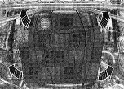
Remove engine cover -arrows-.
Open the extension cover. tank. Remove the front wheels on the left and right. Remove the front right and front left fender liner.
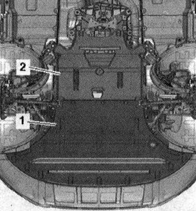
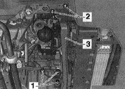
Remove sound insulation panels -1 - and -2-.
Vehicles with front-wheel drive: Move the lock support beam to the service position.
All
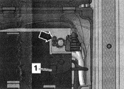
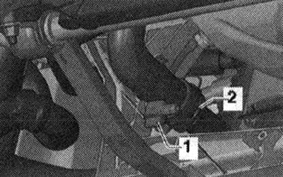
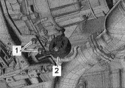
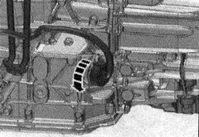
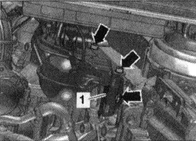
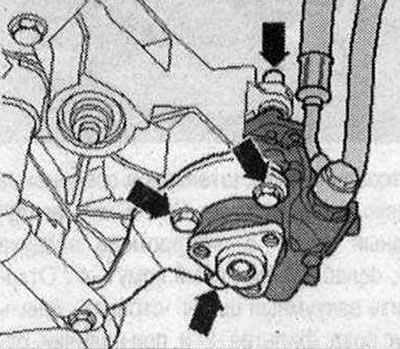
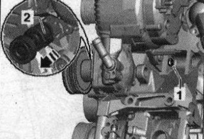
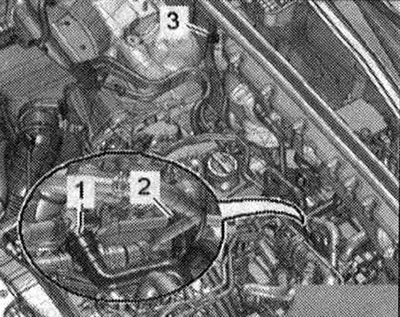
Place service tap tray -VAS 6208- under the engine. Screw the drain valve -1- to the fitting and drain the coolant, then remove the fitting -2- from the radiator by lifting the mounting bracket. Release the coolant hose at the side member.
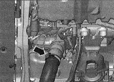
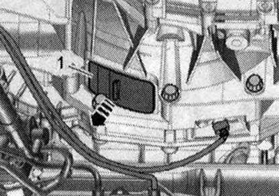
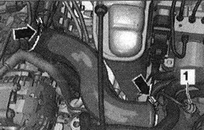
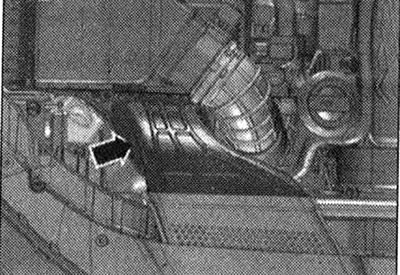
Remove the air inlet hose and press it to the side; to do this, release the clamp -arrow-.
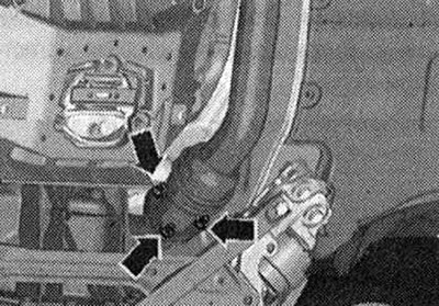
Unscrew the nuts -arrows- of the exhaust pipe.
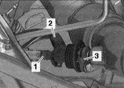
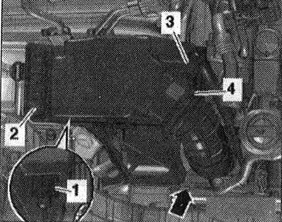
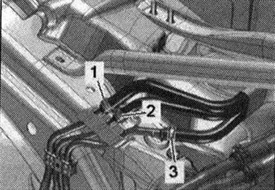
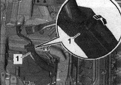
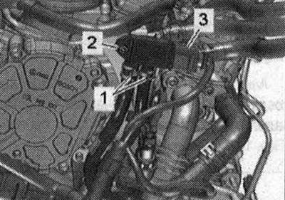
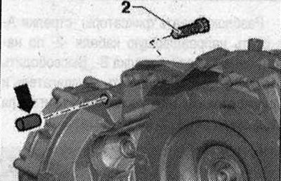
Vehicles with SCR catalytic converter: Disconnect electrical. plug connection -2- and release the electrical connection. the wire. Release clamp -3- and remove reducing agent injector -N474-. -Pos. 1- do not take into account.
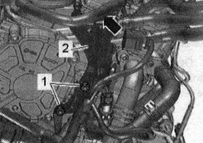
Release exhaust pipe from bracket -2-. -Pos. 1- do not take into account.
All
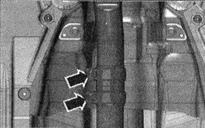
Unscrew the screw connections -arrows-, push the clamping sleeve back and remove the exhaust pipe.
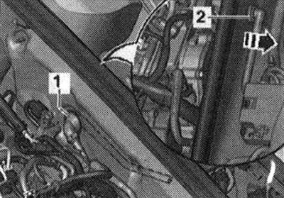
Unscrew the bolt -2- of the diesel particulate filter suspension. -Pos. 1- do not take into account.
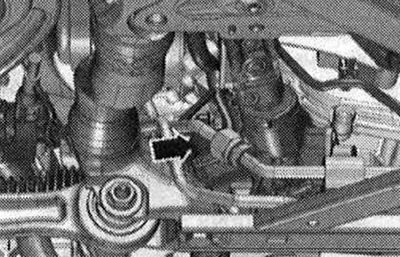
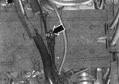
Disconnect el. plug connection -arrow- from the steering gear.
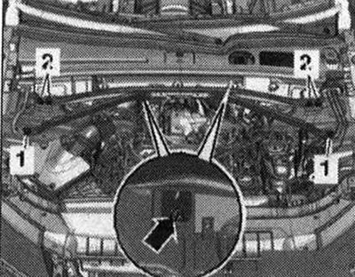
Vehicles with front-wheel drive: Unscrew bolts -1 - and remove the front engine mount. Unscrew bolts on left and right -2- and remove cross member.
All
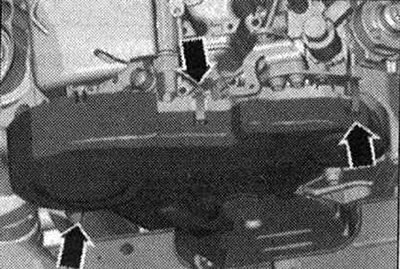
Remove cover -1- from bottom of gearbox -arrow-.
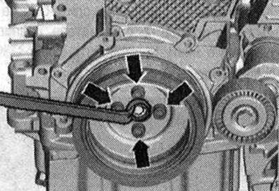
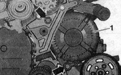
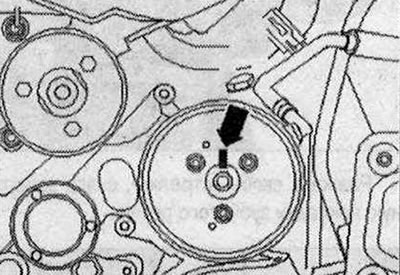
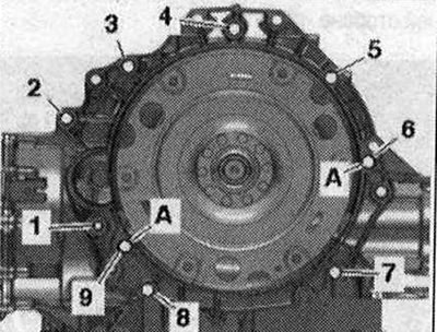
Remove the cap from the vibration damper. Unscrew the 3 bolts -arrow- of the driven disc; to do this, turn the crankshaft at the central bolt of the vibration damper in increments of 120°in the direction of engine rotation.
Vehicles with manual transmission: Unscrew bolts -1, 7, 8, 9, 10- connecting the engine and gearbox. -Pos. A - ignore.
Vehicles with dual clutch gearbox 0B5: Remove starter bolt -1-. Remove the starter from the gearbox and leave it in its installation position. Unscrew the remaining bolts -6...9- securing the gearbox to the engine. -Pos. A - ignore.
All
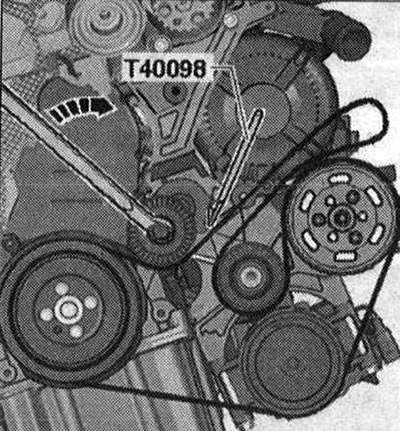
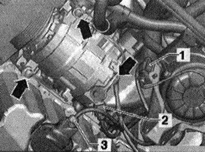
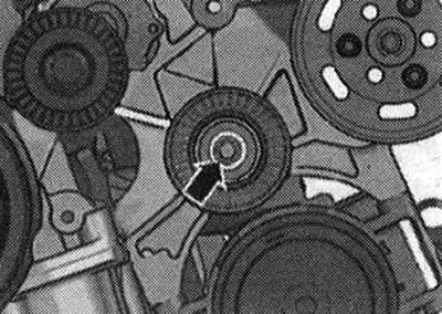
Turn the tensioning element clockwise -arrow-, remove the compressor V-belt from the pulley and secure the tensioning element with the clamp -T40098-. Remove the poly V-belt.
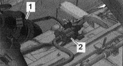
Disconnect el. plug connections -1- and -2- and release the electrical connection. wires. Remove bolts -arrows- for air conditioning compressor. Tie the compressor with the connected lines to the side. -Pos. 3-ignore.
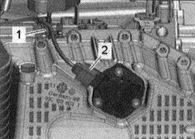
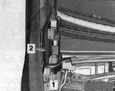
Vehicles with double clutch gearbox 0B5: Disconnect the el. Plug connection -2 for oil level and temperature sender -G266-. -Pos. 1- do not take into account.
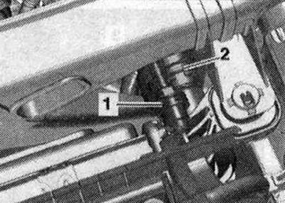
Install a device for pumping out and collecting used oil under the disconnect points. Unscrew union nuts -1- and -2-. Unscrew bolts -arrows- for ATF lines.
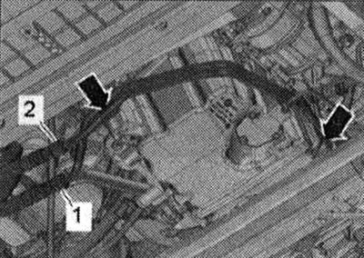
Unscrew bolt -arrow-, disconnect ATF lines -1,2- from gearbox and push to one side. Seal open lines and pipes with clean plugs from the engine plug set -VAS 6122-.
Carefully! Risk of damage to the gearbox control unit (Mechatronik) due to static discharge. Therefore, before carrying out work with electronics. plug connections are required "remove electrostatic charge" with a mechanic. To do this, just touch the car body, heater or lift with your hand. Do not touch the contacts of the gearbox plug with your hands.
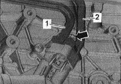
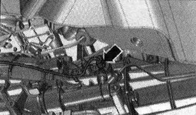
Disconnect el. plug connection from the gearbox by turning the rotary bolt counterclockwise -arrow-. Release the bundle of emails. wires
All
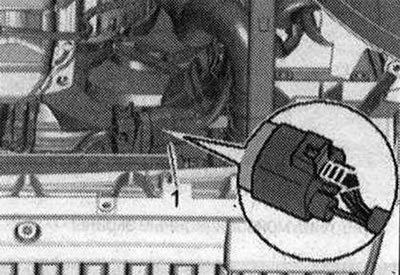
Remove email Plug connection -1- of the radiator fan from the mounting; to do this, push the locking pin backwards -arrow- and press the stopper down. Release the bundle of emails. radiator fan control unit wires.
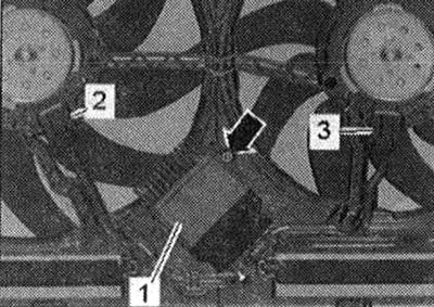
Vehicles with all-wheel drive: Unscrew the bolt -arrow-, unlock the locking mechanism and set aside the radiator fan control unit -J293- -item. 1-. -Pos. 2, 3 - do not take into account.
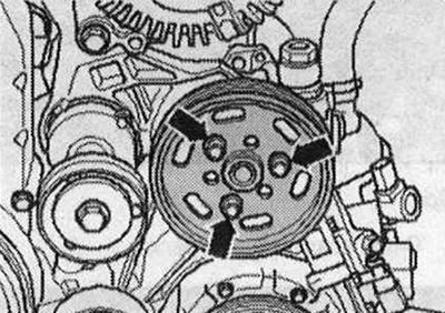
Unscrew the bolts -arrows- while holding the central bolt. Remove vibration damper.
Remove the intermediate roller cap. Unscrew bolt -arrow- and remove intermediate roller.
Unscrew bolts -arrows- and move bracket -1- to rear.
All
Unscrew the nut -arrow- on the right side member and release the ground wires.
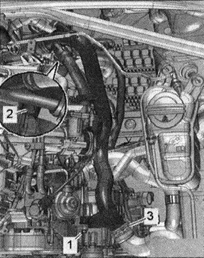
Remove the coolant hoses by unclamping the retaining clips -1- and -3-. -Pos. 2- and -arrows- are ignored.
Remove air hose by loosening hose clamps -arrows-. Disconnect el. Plug connection for charge pressure sender -G31 -/intake manifold air temperature sender -G42- -pos. 1 - and release the el. the wire.
Vehicles with all-wheel drive: Remove bolts -1,2-. Remove the coolant hose by loosening the hose clamp -3-.
Unscrew terminal 30/V+ -pos. 1-. Disconnect el. plug connection -2-.
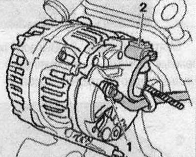
Unscrew bolts -arrows-. Remove the generator -1 - by pressing the coolant pipe at the top left to the side. If the generator jams in the holder, tighten the bolts again up to 2 turns. Gently tap the bolt head with the flat end of a hammer to loosen the alternator mounting bushings.
All
To reinstall, mark the position of the vane pump poly V-belt pulley in relation to the hub -arrow-.
Unscrew the bolts -arrows- and remove the vane pump poly V-belt pulley.
Unscrew the bolts -arrows- and tie the vane pump with the connected hydraulic lines to the side.
Remove the coolant hose by unclamping the retaining clip -2-. -Pos. 1 - do not take into account.
Vehicles with four-wheel drive: Unscrew bolt -1 - and remove tensioner -2- from poly V-belt -arrow-.
Release the brackets -arrows- and remove the toothed belt protective cover.
All
Remove air duct -arrow-.
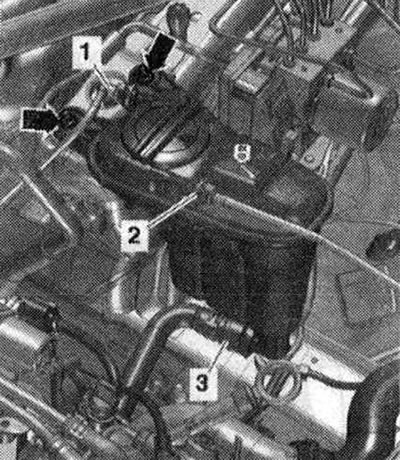
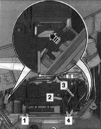
Disconnect el. Plug connection -3- for air mass meter -G70-. Remove air hose from air mass meter -G70- by loosening hose clamp -4-. Disconnect vacuum hose -arrow-. Remove the air housing. filter -2- and, if present, disconnect the el. on its reverse side. plug connection -1 - from the air bypass damper valve. filter -N275-.
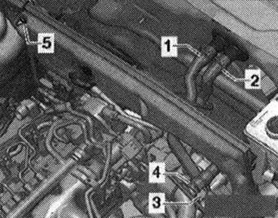
Disconnect fuel supply -3- and return -1,2- lines.
Remove the stretch.
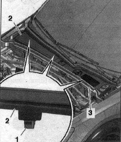
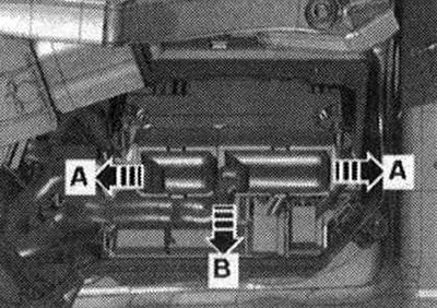
Remove the foam elements -1- and -2- on the left and right, upwards.
Remove gasket -3-. Release the mounting clips -1- from the mountings and remove the plenum chamber cover -2-.
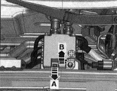
Unlock lock -arrow A- and open cover -arrow B-.
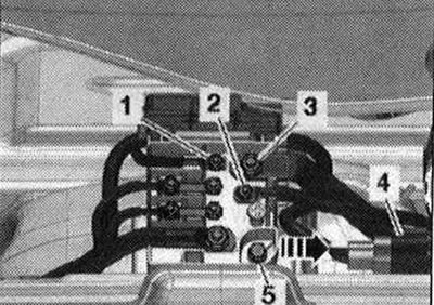
Unscrew the nuts -1...3- el. wires Remove email plug connection -4- from the holder and disconnect it. Unscrew bolt -5- and remove distributor 2 cells. 30 -TV22- from the front wall of the plenum chamber -arrow-.
If present, disconnect the electrical connection. Plug connection from brake servo pressure sensor -G294- -arrow-.
Unlock the clamps from the wheel arch using a 5.5-pos. spanner. 1 - and remove the cable gland -2- upwards. Release the wiring harness -3- to the alternator and starter using the release lever -80 - 200-.
Open the cable duct -1-, to do this, unlock the lock -arrow- and release the electrical bundle. wires
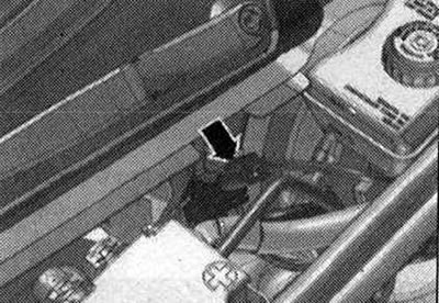
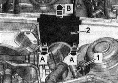
Remove the vacuum connection -1- from the end wall of the plenum chamber; to do this, disconnect the vacuum hose -2- at the rear -arrow-.
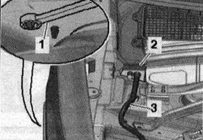
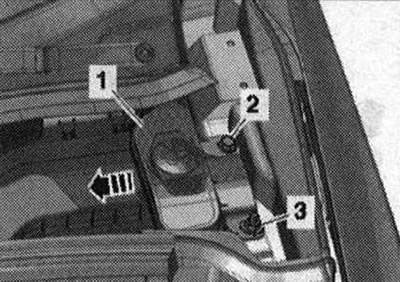
Unscrew bolt -2- and nut -3-. Remove the filler neck -1 - with the filler pipe from the washer fluid reservoir, guiding it through the body opening -arrow-.
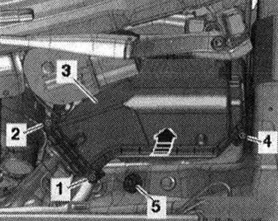
Unscrew the nut -5- and release the ground wire. Unscrew bolts -1,2,4- and remove cover -3- of the engine switching unit. compartment -arrow-.
Unlock the latches -arrows A- and remove the engine control unit -arrow B-.
Disconnect (in the presence of) email plug connection -2-. Disconnect el. plug connections -4- and unscrew the el. wire -3-. Unlock the latches -arrow - and remove the fuse block. B -SB- -pos. 1 -. Disconnect and free the motor wire bundle from the switching unit.
Unlock latches -arrows A- and remove cable guide -2- upwards -arrow B-. Release the bundle of wires, place it on the engine and secure the engine control unit from falling. -Pos. 1- do not take into account.
Vehicles without auxiliary heater: Unscrew nut -5-. Remove the coolant hoses by unclamping the mounting brackets -1,2-. Route the coolant hoses through the front wall of the plenum chamber.
Vehicles with auxiliary heater: Unscrew nut -3-. Remove the coolant hoses by loosening the hose clamps -1,2-. Route the coolant hoses through the front wall of the plenum chamber and release them.
All
Remove the front wall of the drainage box. Disconnect el. Plug connection -3 for differential pressure sender -G505-. Unscrew bolt -2- and release hoses -1- from holder. Move differential pressure sender -G505- to rear.
Release the bundle of emails. wires -arrow-. Unscrew the nuts -1- and remove the holder -2-.
Remove from the holder and disconnect the electrical connection. plug connections.
3. Lambda probe -G39-
4. Exhaust gas temperature sender 3 -G495-
-Pos. 1, 2 - do not take into account. Remove lambda probe -G39- -item. 1 -.
Unscrew the nuts -arrows- and place the particulate filter to the rear.
Vehicles with manual transmission: Disconnect el. plug connection -2- from the reversing light switch -F4- and release the electrical connection. the wire. -Pos. 1.3 - do not take into account.
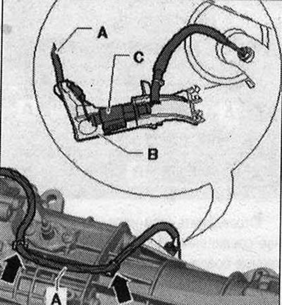
Unclick the email. wire from the gearbox and disconnect the electrical connection. plug connection -C-. -Pos. B- do not take into account.
Disconnect el. plug connection -arrow- from the gearbox neutral sensor -G701- and release the electrical connection. the wire.
Unscrew bolts -2...6- connecting the gearbox and engine. Remove the starter from the gearbox and leave it in its installation position. -Pos. A - ignore. Bolt -2- secures the starter to the gearbox and has an additional spacer sleeve -arrow-.

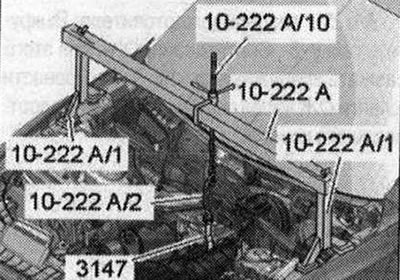
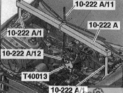
Install the cross member -10 - 222 A- on the shock absorber strut cups on the left and right, as shown in the figure. Secure gearbox mount -3147- to gearbox and use additional hook -10 - 222 A/2- on hook -10 - 222 A/10-. For better understanding, the mounting position is shown with the engine removed.
All
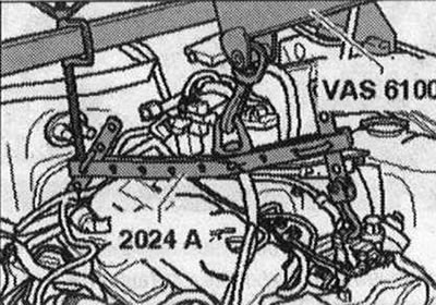
Lightly tighten the engine using the yoke lead screw. Remove the eye of the suspension device -2024 A- by releasing the pin and pressing in the bolt. Reinstall the eyelet into the 4th hole on the front of the hanging fixture. Secure the bolt with a pin. Attach suspension device -2024 A- to the engine and service crane -VAS 6100- as shown in the illustration.
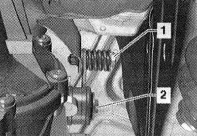
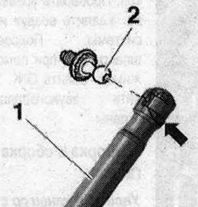
Unscrew the left and right bolts -1- of the engine mount. Unscrew the nut -2- and release the holder with the el. wires. If present, remove the left and right el. plug connection -arrow- from the holder and disconnect them. Raise the engine enough to release the engine mounts. Tighten the traverse lead screw -10 - 222 A-. Risk of damage to hose and cable connections as well as motor. compartment Make sure that all hose and wire connections between the engine, gearbox, subframe and body are disconnected. When removing the engine from the engine. compartment, be careful. When removing the engine, the second mechanic must carefully open the hood, ensuring the maximum opening angle. To do this, lightly pry the retaining spring -arrow- on the left and right with a small screwdriver and remove the gas-filled shock absorber -1- from the top of the ball joints -2-. Disconnect the engine from the gearbox and lift it out of the engine. compartment Press the gas-filled shock absorbers back into the ball joints.
Visitor comments