



Diesel engine 3.0L car Audi Q5 (8R)

Engine characteristics
Letter designations CCWA CCWB Working volume, l 2,967 2,967 Power, kW at rpm 176/3300 155/4000 — 4500 Torque, Nm at rpm 500/1500...3000 500/1500...3000...
Letter designations CCWA CCWB Working volume, l 2,967 2,967 Power, kW at rpm 176/3300 155/4000 — 4500 Torque, Nm at rpm 500/1500...3000 500/1500...3000...

Engine number
The engine number ("engine letter designation" and "serial number") is located in front on the left under the high-pressure pump toothed belt "arrow"....
The engine number ("engine letter designation" and "serial number") is located in front on the left under the high-pressure pump toothed belt "arrow"....

Removal the engine
Note: The engine is removed downwards together with the gearbox and subframe. For disposal or reuse, the coolant must be drained into a clean container. When...
Note: The engine is removed downwards together with the gearbox and subframe. For disposal or reuse, the coolant must be drained into a clean container. When...

Disconnecting the engine and DSG gearbox
The power unit is removed and installed on the "VAS 6131A" lift. Remove connector "2" from the bracket and disconnect it. The figure shows the installation...
The power unit is removed and installed on the "VAS 6131A" lift. Remove connector "2" from the bracket and disconnect it. The figure shows the installation...

Engine installation
Tightening torques (Nm) Note: Tightening torques apply to lightly greased, oiled, phosphated or oxidised nuts and bolts. The use of additional lubricants, such...
Tightening torques (Nm) Note: Tightening torques apply to lightly greased, oiled, phosphated or oxidised nuts and bolts. The use of additional lubricants, such...

Poly V-drive
Poly V-belt drive. I 1. Poly V-belt: Check for wear; before removing, mark the direction of travel with chalk or a felt-tip pen; don't overdo it; when...
Poly V-belt drive. I 1. Poly V-belt: Check for wear; before removing, mark the direction of travel with chalk or a felt-tip pen; don't overdo it; when...

Removal the poly V-belt
Remove the front noise insulation "1". Disconnect the plug connectors "2" and "3". Unscrew the bolt "arrow" and put aside the bracket "1" with the wiring...
Remove the front noise insulation "1". Disconnect the plug connectors "2" and "3". Unscrew the bolt "arrow" and put aside the bracket "1" with the wiring...

Slave disk
Slave disk II 1. Driven disk: with bearing flange; make sure there are no cracks or signs of wear on the bearing flange mating plane, in the holes for the...
Slave disk II 1. Driven disk: with bearing flange; make sure there are no cracks or signs of wear on the bearing flange mating plane, in the holes for the...

Crankshaft
Crankshaft I 1. Crankshaft; 2. Mounting sleeve: 2 pcs.; insert into the cylinder block; 3. Camshaft frame; 4. Bolt; 5. Axial lock washer: only on main bearing...
Crankshaft I 1. Crankshaft; 2. Mounting sleeve: 2 pcs.; insert into the cylinder block; 3. Camshaft frame; 4. Bolt; 5. Axial lock washer: only on main bearing...

Pistons and connecting rods
Pistons and connecting rods 1. Bolts: replace; lubricate the threads and mating surface with oil; 35 Nm + 90°; 2. Connecting rod cap: mark for reassembly; mark...
Pistons and connecting rods 1. Bolts: replace; lubricate the threads and mating surface with oil; 35 Nm + 90°; 2. Connecting rod cap: mark for reassembly; mark...

Timing chain lining installation diagram
Timing chain lining assembly diagram I 1. Crankshaft oil seal on the gearbox side; 2. Engine speed sensor ring gear "G28"; 3. Lower drive chain cover; 4....
Timing chain lining assembly diagram I 1. Crankshaft oil seal on the gearbox side; 2. Engine speed sensor ring gear "G28"; 3. Lower drive chain cover; 4....

Left camshaft timing chain
P.I 1. Axial locking washer for the drive sprocket; 2/13. Bolt; 3/5. Bolt: replace; 5 Nm + 90°; 4. Stabilizer bar: install in the proper position; 6. Left...
P.I 1. Axial locking washer for the drive sprocket; 2/13. Bolt; 3/5. Bolt: replace; 5 Nm + 90°; 4. Stabilizer bar: install in the proper position; 6. Left...

Camshaft timing chain right
Camshaft timing chain right. II 1. Bolt; 2. Support pin of the leading sprocket of the chain drive; 3. Right camshaft timing chain: remove the chain from the...
Camshaft timing chain right. II 1. Bolt; 2. Support pin of the leading sprocket of the chain drive; 3. Right camshaft timing chain: remove the chain from the...

Removal the camshaft drive chains
Gearbox removed. Risk of damage to valves and piston crowns. Crankshaft and camshafts may only be turned with chain drive fully installed. Remove lower chain...
Gearbox removed. Risk of damage to valves and piston crowns. Crankshaft and camshafts may only be turned with chain drive fully installed. Remove lower chain...

Timing phase control
Risk of damage due to the camshaft drive chain jumping. Turn the crankshaft only in the direction of engine rotation. Using the "T40049" key, turn the...
Risk of damage due to the camshaft drive chain jumping. Turn the crankshaft only in the direction of engine rotation. Using the "T40049" key, turn the...

Timing phase adjustment
If it is not possible to fix one of the camshafts, then all the "arrow" bolts of the corresponding camshaft chain sprocket should be unscrewed by approximately...
If it is not possible to fix one of the camshafts, then all the "arrow" bolts of the corresponding camshaft chain sprocket should be unscrewed by approximately...

Timing chain
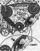
Timing chain 1. Drive sprocket bearing pins 2. Bolt: 45 Nm; 3/4/9/10. Bolt: replace; 5 Nm + 90°; 5. Axial locking washer for the drive sprocket; 6. Left drive...
Timing chain 1. Drive sprocket bearing pins 2. Bolt: 45 Nm; 3/4/9/10. Bolt: replace; 5 Nm + 90°; 5. Axial locking washer for the drive sprocket; 6. Left drive...
Removal the timing chain
Gearbox removed. Remove camshaft drive chains. Remove accessory drive chain. Press chain tensioner shoe "in the direction of arrow" and secure chain tensioner...
Gearbox removed. Remove camshaft drive chains. Remove accessory drive chain. Press chain tensioner shoe "in the direction of arrow" and secure chain tensioner...

Auxiliary drive chain
Auxiliary drive chain 1. Auxiliary drive chain; 2. Leading sprocket of the oil pump chain drive; mounting position: side with inscription facing the engine; 3....
Auxiliary drive chain 1. Auxiliary drive chain; 2. Leading sprocket of the oil pump chain drive; mounting position: side with inscription facing the engine; 3....

Removal the auxiliary drive chain
The gearbox is removed. Remove the lower cover of the drive chains. Install the key "T40049" on the crankshaft from behind, use 2 old bolts "arrows" of the...
The gearbox is removed. Remove the lower cover of the drive chains. Install the key "T40049" on the crankshaft from behind, use 2 old bolts "arrows" of the...

Balance shaft
Balance shaft 1. Plain bearing; 2/7. Bolt: 60 Nm; for unscrewing and screwing use as a counterstop the pin for the fuel pump of the diesel engine "3359"; 3....
Balance shaft 1. Plain bearing; 2/7. Bolt: 60 Nm; for unscrewing and screwing use as a counterstop the pin for the fuel pump of the diesel engine "3359"; 3....

Cylinder head cover
The figure shows the cylinder head cover of the 2nd row of cylinders (left). P.I 1. Cylinder head cover gasket: replacement if damaged or leaking; 2. Cylinder...
The figure shows the cylinder head cover of the 2nd row of cylinders (left). P.I 1. Cylinder head cover gasket: replacement if damaged or leaking; 2. Cylinder...

Removal the left cylinder head cover
Remove the engine casing "arrows". Remove the upper part of the intake manifold. Remove the coolant hose "3" from the radiator, for which lift the clamp....
Remove the engine casing "arrows". Remove the upper part of the intake manifold. Remove the coolant hose "3" from the radiator, for which lift the clamp....

Removal the right cylinder head cover
Remove the engine casing "arrow". Remove the air duct "arrow". Disconnect plug connector "1" of air flow meter "G70". Unscrew bolt "3" and release pressure...
Remove the engine casing "arrow". Remove the air duct "arrow". Disconnect plug connector "1" of air flow meter "G70". Unscrew bolt "3" and release pressure...

Cylinder head
The figure shows the cylinder head of the 2nd row of cylinders (left). P. I 1. Cylinder head seal: replace; installation position: part number facing cylinder...
The figure shows the cylinder head of the 2nd row of cylinders (left). P. I 1. Cylinder head seal: replace; installation position: part number facing cylinder...

Removal the cylinder head
Drain the coolant. Remove the corresponding chain from the camshaft. Remove the upper part of the intake manifold. Remove the corresponding cylinder head...
Drain the coolant. Remove the corresponding chain from the camshaft. Remove the upper part of the intake manifold. Remove the corresponding cylinder head...

Valve mechanism
Frame to left cylinder head - sequence and tightening torque Tighten the bolts and nuts in 2 stages in the sequence shown Stage Bolts/nuts Tightening torque 1...
Frame to left cylinder head - sequence and tightening torque Tighten the bolts and nuts in 2 stages in the sequence shown Stage Bolts/nuts Tightening torque 1...

Removal camshafts — left cylinder head
Remove the corresponding chain from the camshaft. Remove the upper part of the intake manifold. Remove the high-pressure pump toothed belt. Unscrew bolt "1" of...
Remove the corresponding chain from the camshaft. Remove the upper part of the intake manifold. Remove the high-pressure pump toothed belt. Unscrew bolt "1" of...

Removal camshafts — right cylinder head
Remove the corresponding chain from the camshaft. Remove the upper part of the intake manifold. Remove the high-pressure pump toothed belt. Remove the right...
Remove the corresponding chain from the camshaft. Remove the upper part of the intake manifold. Remove the high-pressure pump toothed belt. Remove the right...

Oil pump and lower part of oil pan
Oil pump and lower part of oil pan 1. Oil pan; 2. Bolt: replace; 3. Bolt: self-locking; replace; 8 Nm + 90°; 4. Oil separator; 5. Oil pump: do not disassemble;...
Oil pump and lower part of oil pan 1. Oil pan; 2. Bolt: replace; 3. Bolt: self-locking; replace; 8 Nm + 90°; 4. Oil separator; 5. Oil pump: do not disassemble;...

Removal the oil pump
Removing the lower part of the oil pan. Unscrew the bolts "arrows" and remove the oil separator. Unscrew bolts "1" and "2". Grasp drive shaft "3" of the oil...
Removing the lower part of the oil pan. Unscrew the bolts "arrows" and remove the oil separator. Unscrew bolts "1" and "2". Grasp drive shaft "3" of the oil...

Upper part of the oil pan
Upper part of the oil pan. I 1. Pressure spring; 2. Leash; 3. Oil pump drive shaft; 4. Upper part of the oil pan; 5. Wiring harness bracket; 6/8/19/23. Bolt: 9...
Upper part of the oil pan. I 1. Pressure spring; 2. Leash; 3. Oil pump drive shaft; 4. Upper part of the oil pan; 5. Wiring harness bracket; 6/8/19/23. Bolt: 9...

Oil cooler, pressure regulating valve and oil filter housing
Oil cooler, pressure regulating valve and oil filter housing. II 1. Mounting plate: oil radiator, crankcase ventilation pressure control valve, oil filter...
Oil cooler, pressure regulating valve and oil filter housing. II 1. Mounting plate: oil radiator, crankcase ventilation pressure control valve, oil filter...
Cooling system
Caution. Risk of burns from hot steam and hot coolant. When the engine is warm, the cooling system is under excess pressure. To relieve excess pressure, place...
Caution. Risk of burns from hot steam and hot coolant. When the engine is warm, the cooling system is under excess pressure. To relieve excess pressure, place...

Coolant hose connection diagram
Cars without independent heater Note: Blue = large cooling circuit. Red = small cooling circuit. Orange = EGR cooling circuit. Brown = heating circuit. P. I 1....
Cars without independent heater Note: Blue = large cooling circuit. Red = small cooling circuit. Orange = EGR cooling circuit. Brown = heating circuit. P. I 1....

Draining and filling the coolant
Open the expansion tank cap. Remove noise insulation screens "1" and "2". Install the tray for service cranes "VAS 6208" under the engine. Unscrew the drain...
Open the expansion tank cap. Remove noise insulation screens "1" and "2". Install the tray for service cranes "VAS 6208" under the engine. Unscrew the drain...

Coolant pump and thermostat
Coolant pump and thermostat 1. Bolt: 23 Nm; 2. Bolt: 9 Nm; 3. Cooling system hose: going to the radiator from the bottom right; 4. Connecting pipe with...
Coolant pump and thermostat 1. Bolt: 23 Nm; 2. Bolt: 9 Nm; 3. Cooling system hose: going to the radiator from the bottom right; 4. Connecting pipe with...

Coolant supply pipes
Part 1 1/22. O-ring: replace; 2/20. Nut: 9 Nm; 3. Coolant pipe, front: connecting the coolant hose with a nipple connector; 4/14/17. Bolt: 9 Nm; 5. Sealing...
Part 1 1/22. O-ring: replace; 2/20. Nut: 9 Nm; 3. Coolant pipe, front: connecting the coolant hose with a nipple connector; 4/14/17. Bolt: 9 Nm; 5. Sealing...

Removal the coolant temperature sensor
Removal the coolant temperature sensor "G62" Cold engine. Briefly open the expansion tank cap to relieve residual pressure in the cooling system. Remove the...
Removal the coolant temperature sensor "G62" Cold engine. Briefly open the expansion tank cap to relieve residual pressure in the cooling system. Remove the...

Radiator and radiator fan
Radiator and radiator fan 1. Used radiator fans "J293"; 2. Bolt: 2.5 Nm; 3/24. Bolt: 5 Nm; 4. Fan frame; 5. Radiator fan "V7": with built-in and separate used...
Radiator and radiator fan 1. Used radiator fans "J293"; 2. Bolt: 2.5 Nm; 3/24. Bolt: 5 Nm; 4. Fan frame; 5. Radiator fan "V7": with built-in and separate used...

Removal the fan frame
Remove the front noise insulation "1". Install the tray for the service cranes "VAS 6208" under the engine. Unscrew the plug "arrow" of the drain hole on the...
Remove the front noise insulation "1". Install the tray for the service cranes "VAS 6208" under the engine. Unscrew the plug "arrow" of the drain hole on the...

Turbocharger — removal and installation
Turbocharger. I 1. Connecting pipe: to the EGR radiator changeover valve; 2/28/37 Gasket: Replace; 3. Intermediate flange; 4/38. Bolt: 25 Nm; 5. Cooling system...
Turbocharger. I 1. Connecting pipe: to the EGR radiator changeover valve; 2/28/37 Gasket: Replace; 3. Intermediate flange; 4/38. Bolt: 25 Nm; 5. Cooling system...

Intercooler — details
Intercooler 1. Intercooler; 2/4/8/10/11/13/22/24. Hose clamp: reinforced; 5.5 Nm; 3. Air duct hose: to intercooler; before installation, clean from oil and...
Intercooler 1. Intercooler; 2/4/8/10/11/13/22/24. Hose clamp: reinforced; 5.5 Nm; 3. Air duct hose: to intercooler; before installation, clean from oil and...

Injection system
Installation location diagram Right side of the engine compartment 1. Air filter bypass flap valve "N₂75": units (bypass flap with air filter bypass flap valve...
Installation location diagram Right side of the engine compartment 1. Air filter bypass flap valve "N₂75": units (bypass flap with air filter bypass flap valve...

System overview
Attention. When carrying out any work on the fuel system, familiarize yourself with the rules for maintaining cleanliness and instructions. Strictly observe...
Attention. When carrying out any work on the fuel system, familiarize yourself with the rules for maintaining cleanliness and instructions. Strictly observe...

Fuel system
Fuel system 1. Fuel return pipe from pump injectors: to the fuel tank; the return fuel line must not be kinked, damaged or clogged; 2. Fuel supply pipe to the...
Fuel system 1. Fuel return pipe from pump injectors: to the fuel tank; the return fuel line must not be kinked, damaged or clogged; 2. Fuel supply pipe to the...

Air filter
Air filter 1. Hose clamp: 3.5 Nm; 2. Air duct hose: to throttle control module "J338"; when installing, pay attention to the markings; pre-install the air duct...
Air filter 1. Hose clamp: 3.5 Nm; 2. Air duct hose: to throttle control module "J338"; when installing, pay attention to the markings; pre-install the air duct...

Removal the air filter insert
Disconnect plug "2" from the air flow meter "G70". Remove the air duct hose from the air flow meter "G70", to do this, loosen the hose clamp "3". Unscrew the...
Disconnect plug "2" from the air flow meter "G70". Remove the air duct hose from the air flow meter "G70", to do this, loosen the hose clamp "3". Unscrew the...

Intake manifold parts and components
The figure shows the upper and lower parts of the intake manifold on the left. Intake manifold parts and components 1. Fastening clamp: 5.5 Nm reinforced; 2....
The figure shows the upper and lower parts of the intake manifold on the left. Intake manifold parts and components 1. Fastening clamp: 5.5 Nm reinforced; 2....

Removal the upper part of the intake manifold
Remove the engine cover. Remove the oil dipstick "1" from the guide tube. Remove the air duct hose by loosening the hose clamp "3". Unscrew the bolt "2" and...
Remove the engine cover. Remove the oil dipstick "1" from the guide tube. Remove the air duct hose by loosening the hose clamp "3". Unscrew the bolt "2" and...

Lower part of the left intake manifold
Remove the upper part of the intake manifold. Carefully press out the connecting rod of the intake manifold flap motor "V275", "arrow". Disconnect the plug...
Remove the upper part of the intake manifold. Carefully press out the connecting rod of the intake manifold flap motor "V275", "arrow". Disconnect the plug...

Lower part of the right intake manifold
Remove the engine casing. Remove the upper part of the intake manifold. Unscrew the bolts "arrows" and remove the protective screen of the high-pressure line....
Remove the engine casing. Remove the upper part of the intake manifold. Unscrew the bolts "arrows" and remove the protective screen of the high-pressure line....

Removal injectors (piezo injectors)
Instructions: The following shows the removal and installation of the injectors on the left bank of cylinders 2. Stage of work only on cylinder bank 1: remove...
Instructions: The following shows the removal and installation of the injectors on the left bank of cylinders 2. Stage of work only on cylinder bank 1: remove...

Toothed belt of injection pump
Toothed belt of injection pump 1. Front timing belt cover: Install at the bottom and fix at the side; 2. Nut: 70 Nm; 3/12. Bolt: 23 Nm; 4. High pressure pump...
Toothed belt of injection pump 1. Front timing belt cover: Install at the bottom and fix at the side; 2. Nut: 70 Nm; 3/12. Bolt: 23 Nm; 4. High pressure pump...

High pressure fuel pump
Caution! To avoid dry running of the high-pressure fuel pump and to quickly start the engine after replacing parts, the following points must be observed....
Caution! To avoid dry running of the high-pressure fuel pump and to quickly start the engine after replacing parts, the following points must be observed....

Lambda probe
Lambda probe 1. Diesel particulate filter; 2. Lambda probe "G39" with heating for lambda probe "Z19": new lambda probes are covered with mounting paste; when...
Lambda probe 1. Diesel particulate filter; 2. Lambda probe "G39" with heating for lambda probe "Z19": new lambda probes are covered with mounting paste; when...

Exhaust system
Muffler 1. Y-pipe: installed at the factory as one piece with the rear mufflers, in case of repair it is replaced separately; the cut between the tee and the...
Muffler 1. Y-pipe: installed at the factory as one piece with the rear mufflers, in case of repair it is replaced separately; the cut between the tee and the...

Exhaust manifold
The figure shows the exhaust manifold with the intermediate pipe of the 2nd row of cylinders (left). P. I 1. Nut: replace; lubricate with heat-resistant paste;...
The figure shows the exhaust manifold with the intermediate pipe of the 2nd row of cylinders (left). P. I 1. Nut: replace; lubricate with heat-resistant paste;...

Parts and components of the exhaust gas recirculation system
Exhaust gas temperature sensor I 1. Diesel particulate filter; 2. Lambda probe "G39" with heating element of lambda probe "Z19"; 3. Sensor 1 of the exhaust gas...
Exhaust gas temperature sensor I 1. Diesel particulate filter; 2. Lambda probe "G39" with heating element of lambda probe "Z19"; 3. Sensor 1 of the exhaust gas...
This section is available on russian, bulgarian, belarusian, ukrainian, serbian, croatian, romanian, polish, slovak, hungarian
Share information:
- General information
- Operating instructions
- Maintenance
- Power unit
- Diesels 3.0 l (BUG, BUN, CAS)
- Diesels 3.0 l (CATA, CCMA)
- Diesels 3.0 l (CJGA/CJGC)
- Diesels 4.2 l (BTR, CCFA/CCFC)
- Cooling system
- Fuel and exhaust system
- Engine management system
- Starting and charging
- Transmission
- Automatic gearbox
- Drive shafts
- Chassis
- Brake system
- Front suspension
- Rear suspension
- Steering system
- Body
- Air conditioner
- Exterior
- Interior
- Electrical equipment
- Equipment and devices
- Electrical circuits
- General information
- User manual
- Power unit
- Petrol engine 2.0 l
- Petrol engine 3.2 l
- Fuel system (petrol)
- Diesel 2.0 liter (CA)
- Diesel 2.0 liter (CG/CJ/CM)
- Diesel engine 3.0 l
- Fuel system (diesel)
- Transmission
- Manual gearbox 0B1
- Manual gearbox 0B2
- Automatic gearbox 0B5
- Automatic gearbox 0B6
- Chassis
- Front suspension
- Rear suspension
- Brake system
- Steering
- Body
- Exterior
- Interior
- Doors, locks and windows
- Safety system
- Ventilation and heating
- Electrical equipment
- Power devices
- Equipment and devices
- Lighting and alarm
- Audio system
- Electrical circuits