
Table of contents: Installation location diagram ↓ Left side of the engine compartment ↓ Installation location of the used… ↓ Accelerator Pedal Position Sensor… ↓ Coolant temperature sensor "G62" ↓ Fuel pressure sensor "G247" "1" row… ↓ Fuel pressure regulating valve 1… ↓ Radiator pump of the recirculation… ↓ Oil pressure sensor for low pressure… ↓ Boost pressure sensor "G31" with… ↓ Engine speed sensor "G28-2" ↓ Exhaust gas temperature sensor 1… ↓
Installation location diagram
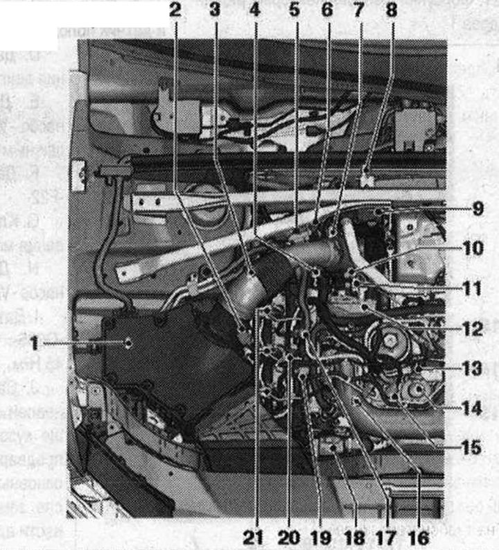
Right side of the engine compartment 1. Air filter bypass flap valve "N₂75": units (bypass flap with air filter bypass flap valve "N₂75") are not installed in all kit variants and not for all countries; if the bypass damper is installed, it is located in the air filter housing, and the air filter bypass damper valve "N₂75" is fixed outside on the air filter housing; 2. Air flow meter "G70"; 3. Hall sensor "G40" (camshaft position sensor); 4. Fuel pressure regulating valve "N₂76"; 5. Pressure sensor 1 for exhaust gas "G450": after replacement it is necessary to carry out adaptation; 6. Electrical plug connection: exhaust gas temperature sensor 4 "G648"; 7. Coolant temperature sensor "G62"; 8. Sensor 4 exhaust gas temperature "G648"; 9. Used turbocharger 1 "J724"; 10. Connector of the temperature sensor in the exhaust gas recirculation system "G98"; 11. Electrical connector of exhaust gas temperature sensor 1 "G235": exhaust gas temperature sensor 1 "G235"; 12. Intake manifold flap motor "V157": cylinder bank 1; 13. Fuel line pipe of high pressure circuit; 14. High pressure fuel pump: with fuel metering valve "N₂90"; after replacing the fuel injection pump, it is "necessary" to carry out the first refueling (to prevent dry running); 15. Fuel metering valve "N₂90": do not open; installed directly in the high pressure fuel pump; 16. Oil pressure sensor for low pressure "F378"; 17. Fuel temperature sensor "G81"; 18. EGR radiator pump "V400"; 19. Coolant temperature sensor at the radiator outlet "G83"; 20. Pressure reducing valve: in the drainage pipes of the 1st and 2nd rows of cylinders; function of the pressure reducing valve, to provide residual pressure in the return fuel lines (scope of control) approx. 10 bar; this amount is necessary for the operation of piezo injectors; the pressure reducing valve should only be replaced together with the return fuel lines; after replacement, let the engine run for about 2 minutes at idle speed to remove air from the fuel system; 21. Nozzles (piezo injectors): cylinder bank 1
Left side of the engine compartment
Nodes A through J are not shown in the exploded view.
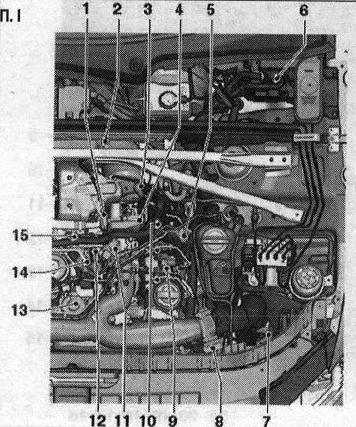
P. I 1. Plug connector of the exhaust gas temperature sensor 3 "G495"; 2. Sensor 3 exhaust gas temperature "G495": installed behind the catalytic converter; 45 Nm; 3. Lambda probe "G39" with heating for lambda probe "Z19": 50 Nm; 4. Intake manifold flap motor 2 "V275": cylinder bank 2; 5. Lambda probe plug connector "G39"; 6. Used engine "J623"; 7. Boost pressure sensor "G31": with intake air temperature sensor "G42"; 8. Used throttle valve "J338": 9 Nm; 9. Fuel pressure sensor "G247": 30 Nm; 10. Nozzles (piezo injectors): cylinder bank 2; 11. EGR radiator changeover valve "N345"; 12. Temperature sensor in the exhaust gas recirculation system "GOS"; IS. High pressure fuel pump: with fuel metering valve "N₂90"; after replacing the fuel injection pump, it is "necessary" to carry out the first refueling (to prevent dry running); 14. EGR servomotor "V338"; 15. Vacuum regulator: switching flaps from the EGR cooler; A. Low power heating relay "J359" and high power heating relay "J360"; B. Brake light switch "F" and foot brake pedal position switch "F47": in the footwell on the brake pedal; C. Accelerator pedal position sensor "G79" and accelerator pedal position sensor 2 "G185"; D. Engine speed sensor "G28"; E. Additional fuel pump "V393": under the right protective screen of the bottom; F. Oil pressure sensor "F22"; G. Oil pressure regulating valve "N428"; H. Additional fuel pump "V393"; I. Exhaust gas temperature sensor 1 "G235": on turbocharger; 45 Nm; J. Diesel particulate filter: installed at the bottom outside on the underbody of the vehicle; common unit with pre-connected main catalyst; after replacement, adaptation must be carried out
After replacing the exhaust gas pressure sensor 1 "G450" and/or the diesel particulate filter, it is necessary to carry out adaptation. (The workflow is also described in the Guided Functions.) Select the relevant vehicle in Guided Fault Finding. Press the "Go" button. Press "Functions/Node selection". Select "Engine". "01 - Systems with self-diagnosis". "01 - Engine electronics J623". Select "01 - Functions of engine electronics". "01 - Adapt diesel particulate filter parameters".
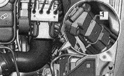
Installation location of the used engine "J623"
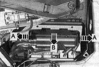
In the left switching unit in the engine compartment.
Accelerator Pedal Position Sensor "G79" and Accelerator Pedal Position Sensor 2 "G185"
The accelerator pedal position sensor "G79" and the accelerator pedal position sensor 2 "G185" are integrated into the accelerator pedal module and cannot be replaced separately.
Coolant temperature sensor "G62"
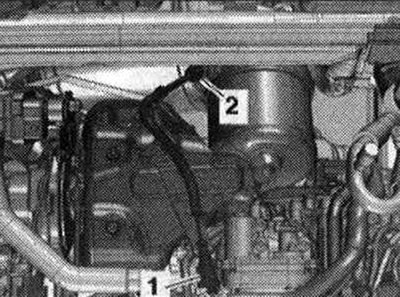
Fuel pressure sensor "G247" "1" row of cylinders 2
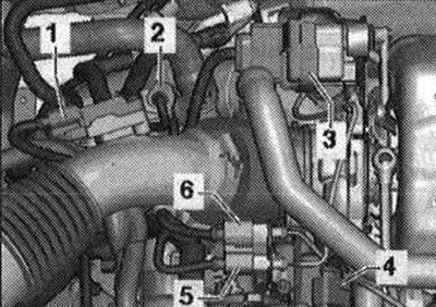
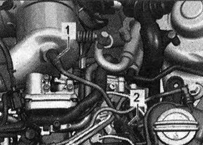
Installation locations on cylinder bank 1 1. Hall sensor "G40"; 2. Fuel pressure regulating valve "N₂76"; 3. Fuel temperature sensor "G81"; 4. Radiator outlet coolant temperature sensor "G83"; 5, 6. Injection modules (piezo injectors)
Fuel pressure regulating valve 1 "N₂76" on cylinder bank "1"
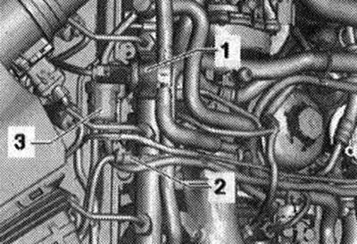
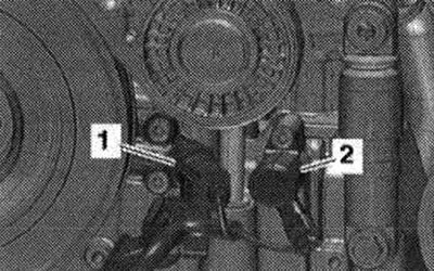
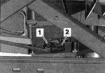
Details of the right bank of cylinders 1. Fuel temperature sensor "G81"; 2. Coolant temperature sensor at the radiator outlet "G83"; 3. Fuel backflow support valve
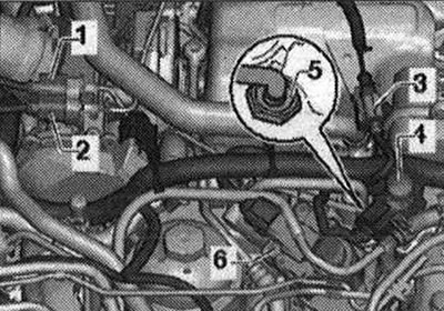
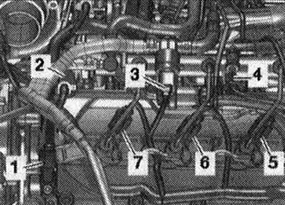
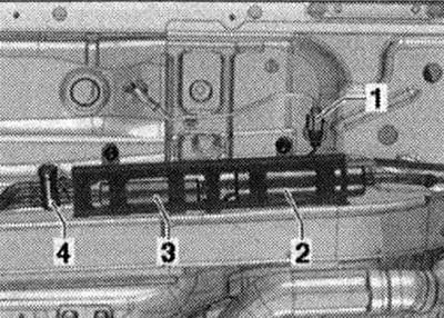
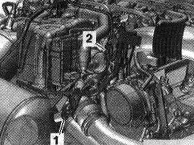
Installation locations 1. Electrical connector of the temperature sensor in the exhaust gas recirculation system "G98"; 2. Electrical connector of exhaust gas temperature sensor 1 "G235"; 3. Electrical connector of the exhaust gas temperature sensor 3 "G495"; 4. EGR radiator changeover valve "N345"; 5. Temperature sensor in the exhaust gas recirculation system "G98"; 6. Servomotor of the exhaust gas recirculation system "V338"
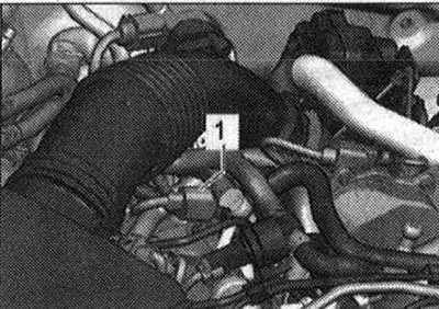
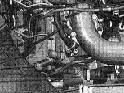
Radiator pump of the recirculation system OF "V400--1"
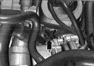
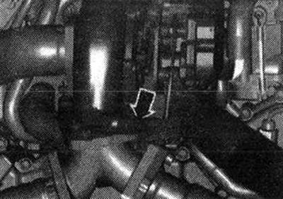
Oil pressure sensor for low pressure "F378" "arrow"
Oil pressure adjustment 1. Oil pressure sensor "F22"; 2. Oil pressure regulating valve "N428"
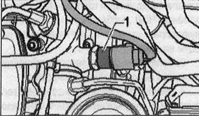
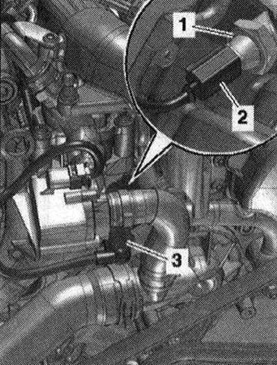
Boost pressure sensor "G31" with intake manifold temperature sensor "G42" "1" in the intercooler
Installation locations 1. Pressure sensor 1 for exhaust gas "G450"; 2. Electrical connector of the exhaust gas temperature sensor 4 "G648"; 3. Used turbocharger 1 "J724"; 4. Intake manifold flap motor "V157"; 5. Electrical connector of exhaust gas temperature sensor 1 "G235"; 6. Electrical connector of the temperature sensor in the exhaust gas recirculation system "G98"
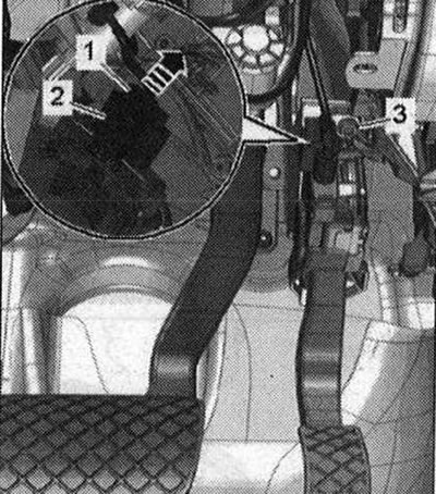
Additional fuel pump "V393" 1. Plug connector of additional fuel pump "V393" (installation location may vary); 2. Fuel filter; 3. Additional fuel pump "V393"; 4. Heating valve
Engine speed sensor "G28-2"
Installation location of the lambda probe "G39" 1. Lambda probe "G39"; 2. Lambda probe plug connector "G39"
Exhaust gas temperature sensor 1. Sensor 4 exhaust gas temperature "G648"; 2. Electrical connector of the exhaust gas temperature sensor 4 "G648"
Exhaust gas temperature sensor 1 "G235" "arrow"
Exhaust gas temperature sensor 1. Electrical connector of the exhaust gas temperature sensor 3 "G495"; 2. Sensor 3 exhaust gas temperature "G495"