
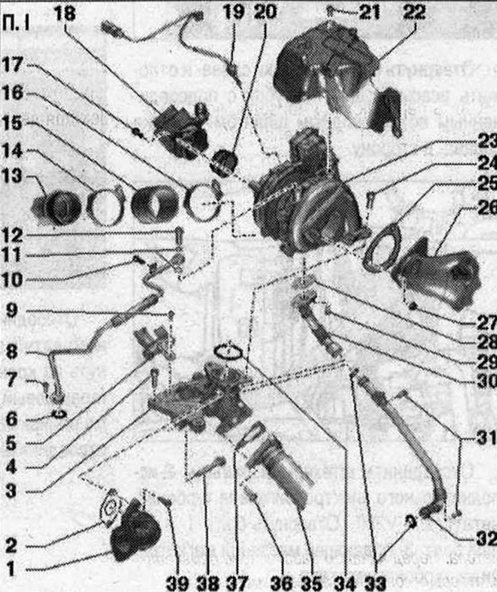
Turbocharger. I 1. Connecting pipe: to the EGR radiator changeover valve; 2/28/37 Gasket: Replace; 3. Intermediate flange; 4/38. Bolt: 25 Nm; 5. Cooling system pipe rear right; 6. Sealing ring: replace; 7/9/10/17/21/39. Bolt: 9 Nm; 8. Oil supply line: from the cylinder block; 11. O-rings: replace; 12. Hollow bolt: 15 Nm; 13. Right airway tube; 14/16. Hose clamp: reinforced; 5.5 Nm; 15. Air duct hose: from turbocharger to right air duct; 18. Air hose connection: from air flow meter "G70" to turbocharger; before installation, clean from oil and grease; 19. Exhaust gas temperature sensor 1 "G235"; 20. Sealing cuff: replace if damaged; 22. Turbocharger heat shield; 23. Turbocharger; 24. Bolt: replace; lubricate with heat-resistant paste; 30 Nm + 90°; 25. Gasket: replace; 26. Diesel particulate filter; 27. Nut; 29. Bolt: lubricate with heat-resistant paste; pre-tighten to 7 Nm; 9 Nm; 30. Upper oil return pipe: from turbocharger; 31. Bolts: 9 Nm; 32. Lower oil return line pipe: to cylinder block; 33. O-rings: replace; 34. Gasket: replace; 35. Intermediate tube; 36. Bolt
Removal
Caution! If the turbocharger has mechanical damage (for example, damage to the impeller), it is not enough to simply replace the turbocharger. To prevent further damage, the following work must be performed. Check the air filter housing and filter element, as well as the air supply hoses for contamination. Check the entire boost air supply system and intercooler for foreign objects. If foreign objects are found in the boost air system, clean the boost air supply lines and replace the intercooler if necessary.
Remove the engine casing "arrows". Remove the brace. Remove the air duct "arrow". Disconnect the plug "1" of the air flow meter "G70". Unscrew the bolt "3" and release the pressure sensor 1 EG "G450" "pos. 4" on the air duct pipe. Disconnect and release the plug "2" of the temperature sensor 4 "G648" on the air duct pipe. Remove the air hose with the air flow meter "G70", to do this, loosen the hose clamp "5" and loosen the clamps "arrows".
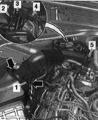
Loosen bolt "2" and unscrew bolt "3" a few turns. Remove the air duct tube from the air duct hose by loosening the hose clamp "1".
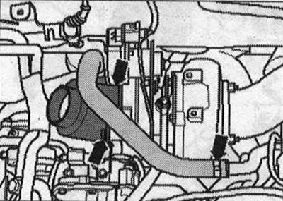
Loosen the bolts "arrow on the left" and set the suction pipe with the connected air duct hose "arrow on the right" aside.
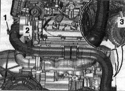
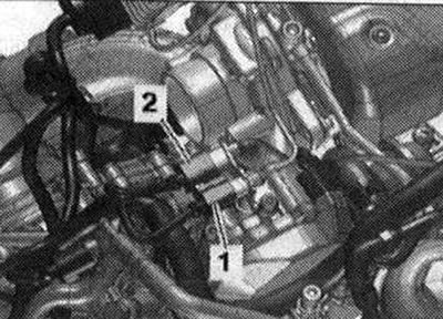
Disconnect plug connector "2-is" of turbocharger auxiliary electric motor 1 "V280". Unscrew bolt "1" and hollow bolt "3" of the oil supply line on the turbocharger
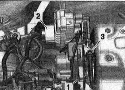
Remove connector "2" from the bracket and disconnect it. Ignore "Pos. 1".
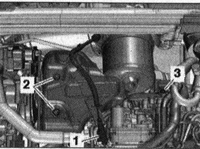
Release and disconnect plug connector "1" of exhaust gas temperature sensor 3 "G495". Unscrew bolts "2" and "3". Remove the turbocharger heat shield.
Unscrew the "arrow" nuts and remove the particulate filter from the turbocharger.
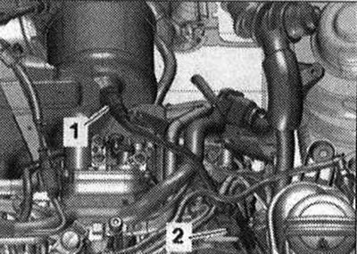
Disconnect plug connector "1" (black) of exhaust gas temperature sensor 1 "G235". Remove plug connector "2" (orange) of temperature sensor in the exhaust gas recirculation system "G98" from the bracket and disconnect the connector.
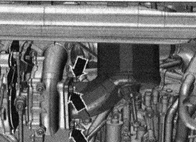
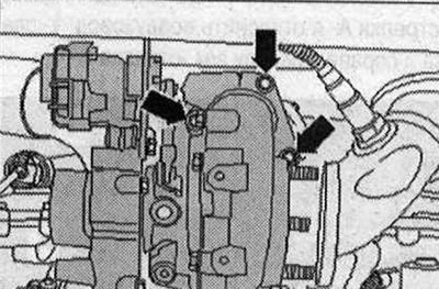
Loosen the turbocharger arrow bolts.
Risk of damage to both oil return pipes. The upper oil return pipe "3" secured to the turbocharger must be carefully removed from the lower oil return pipe "5". To prevent both oil return pipes from bending, the turbocharger "4" must be removed from the side upwards, slightly tilting it in different directions.
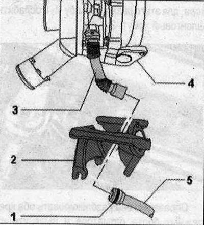
- 1. Sealing ring
- 2. Intermediate flange
Remove the turbocharger. To prevent contamination, close the disconnected lines and pipes on the intercooler with a clean plug from the plug kit for the "VAS 6122" engine. To avoid damage, the removed turbocharger must not be placed on top of the oil return line.
Installation
Replace seals, lip seals and sealing rings. When installing, install all heat-insulating cuffs in their original places. Fill the turbocharger with oil through the oil supply line nipple. Hose nipples, air ducts and hoses must be cleaned of oil and grease before installation. Secure all hose connections with hose clamps of the appropriate series. To ensure reliable fastening of the air duct hoses to the nipples, treat the threaded connections of the already used clamps with a rust remover. To ensure that oil is supplied to the turbocharger, let the engine run for about 1 minute at idle speed after installing the turbocharger; do not run the engine at high speed. Install a new sealing ring "1" on the lower section "5" of the oil return line. Lubricate the sealing ring and the inner mating surface at the upper section "3" of the oil return line. When installing the turbocharger "4", pass the upper section "3" of the oil return line through the intermediate flange?2- and connect to the lower section "5" of the oil return line. Risk of damage to the sealing ring. Carefully push the upper section "3" of the oil return line onto the lower section "5" of the oil return line. Screw on the turbocharger "arrows". Installation is in the reverse order, while observing the following. Install the particulate filter. Install the exhaust gas pressure sensor 1 "G450". Install the brace.
Removal the intermediate flange
Remove the diesel particulate filter. Remove the turbocharger. Unscrew bolts "1" and "3". Ignore "Pos. 2" and "arrows".
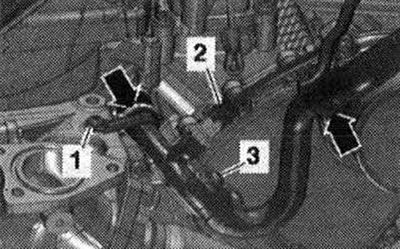
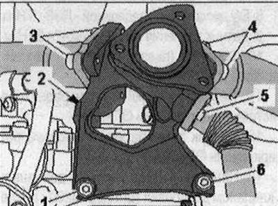
Unscrew bolts "3" (3 pcs.), "4" (3 pcs.), "5" (2 pcs.), as well as "1,2,6" and remove the intermediate flange.
Installation
Installation in reverse order. Replace seals. Install turbocharger.