
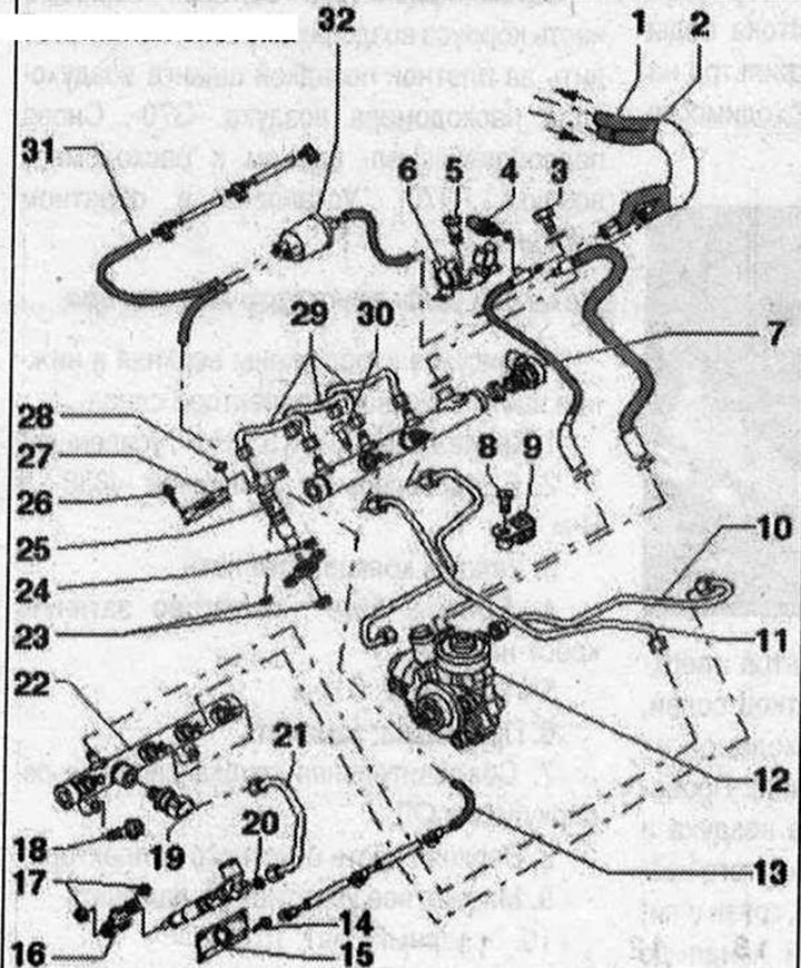
Fuel system 1. Fuel return pipe from pump injectors: to the fuel tank; the return fuel line must not be kinked, damaged or clogged; 2. Fuel supply pipe to the booster pumps: coming from the fuel filter; 3. Hollow screw of the return fuel pipeline; 4. Fuel temperature sensor "G81"; 5. Bolt; 6/9. Bracket; 7. Fuel pressure regulating valve "N₂76": installed on cylinder bank 1; do not reuse; 8. Bolt; 10. High pressure fuel line: between the high pressure fuel pump and the fuel rail; 11. High pressure fuel line: between fuel rail of cylinder bank 1 and fuel rail of cylinder bank 2; before reusing the "high pressure fuel line", visually inspect the seals for damage, such as nicks or corrosion; if damaged, always replace; the faulty high pressure line must be replaced; 12. High pressure fuel pump: with fuel metering valve "N₂90"; after replacing the fuel injection pump, it is necessary to carry out the first refueling (to prevent dry running); 13. Fuel lines leaking fuel (Return fuel line): Do not disassemble the return fuel lines - they can only be replaced together with the pressure reducing valve; after replacement, let the engine idle for 2 minutes to remove air from the fuel system and then check the return fuel lines for leaks; 14. Bolt: injector cover to cylinder head cover; 5.5 Nm; 15. Injection module cover; 16. Seizing: disassembled injectors and seizings to be assembled must be reinstalled in the cylinders exclusively in the same places; if the nozzle (injector) is replaced, the grip must also be updated; 17. Hexagonal flange nut of clamp bracket: 10 Nm; 18. Fuel rail bolt (high pressure receiver) row of cylinders 2:22 Nm; 19. Fuel pressure sensor "G247": 30 Nm; installed on cylinder bank 2; 20. Sealing cuff: replace; 21. High pressure fuel lines: for the second bank of cylinders; 25 Nm; 22. Fuel rail (High pressure energy accumulator): for the second row of cylinders; 23. O-rings: replace; 24. Hexagonal flange nut of clamp bracket: 10 Nm; 25. Nozzle (piezo injector): the listed components and seals, or sealing cuffs, must be replaced each time they are removed or installed: "copper washer", "injector seat sealing cuff", "injector return line sealing cuff"; the following parts and seals, as well as the O-rings, must be replaced each time the injector is replaced: "clamp", "copper washer", "injector seat O-ring", "injector return line O-ring"; before reusing the "high pressure injection line", visually inspect the seals for damage, e.g. transverse grooves, corrosion; if damaged, always replace; removed injectors, high-pressure injection lines and clamps that are reinstalled must be installed exclusively on the same cylinder; 26. Bolt: injector cover to cylinder head cover; 5.5 Nm; 27. Injection module cover; 28. Sealing cuff: replace; 29. High pressure fuel lines: for cylinder bank 1; 30. Bolt: fuel rail (high pressure receiver) row of cylinders 1; 22 Nm; 31. Leakage fuel lines (Return fuel line): Do not disassemble the return fuel lines - they can only be replaced together with the pressure reducing valve; after replacement, let the engine idle for 2 minutes to remove air from the fuel system and then check the return fuel lines for leaks; 32. Pressure reducing valve: in the drainage pipes of the 1st and 2nd rows of cylinders; the function of the pressure reducing valve is to ensure residual pressure in the return fuel lines (scope of control) approx. 10 bar; this quantity is necessary for the operation of Piezo "in" injectors; the pressure reducing valve should only be replaced together with the return fuel lines; after replacement, let the engine run for 2 minutes at idle speed to remove air from the fuel system; check the pressure reducing valve
Information obtained from this resource Audimanual.ru