
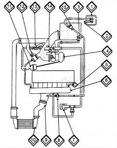
1 Activated carbon filter
2 Ventilation line from the fuel tank
3 Check valve for activated carbon tank
4 Exhaust-driven turbocharger
5 Fuel pressure regulator
6 Intake manifold (fuel line)
7 Engine crankcase ventilation
8 Check valve for activated carbon tank
9 Connection on the throttle body
10 Charge air cooler
11 Charge air cooler pressure tank
12 Coasting cut-off valve
13 Magnetic valve for limiting discharge pressure
14 Crankcase ventilation pressure limiting valve
15 Electrically controlled valve for activated carbon filter.
A turbocharger provides better cylinder filling when the fuel-air mixture is forced into the cylinders under pressure. The turbocharger is driven using the energy of the exhaust gases.
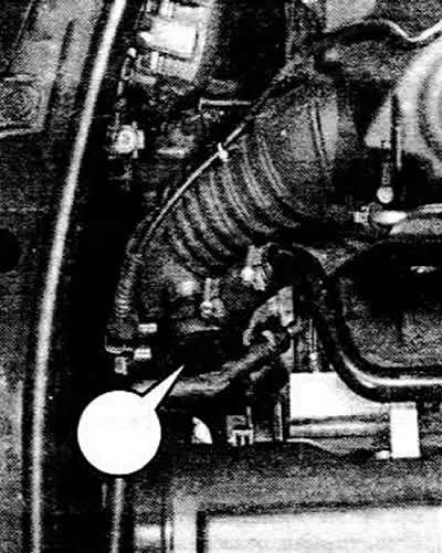
The arrow shows the crankcase ventilation system pressure limiting valve.
To keep the pressure generated within certain limits, a boost pressure regulator must be installed in the system. Its task is to open the magnetic valve when the pressure is too high, so that only part of the flow can pass through the turbine wheel of the turbocharger.
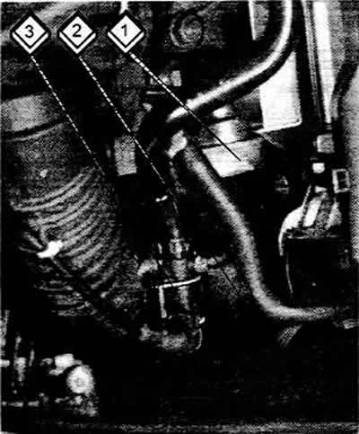
1 Capacity of charge air cooler
2 Coasting cut-off valve
3 Magnetic valve for limiting the supercharger pressure
In order to keep the regulation under control under all operating conditions, the injection/ignition control unit is activated. An electropneumatic valve controls the turbocharger bypass via a booster tank. When the valve is open, the boost pressure drops. The control unit also ensures that the required boost pressure is always provided. In addition, the height controller is connected to the control unit (installed in the electronic unit in the engine compartment), which ensures that when operating the vehicle at high altitude, the reduced air density does not interfere with the normal operation of the turbocharger. In this case, the boost pressure is increased so that, while the amount of fuel injected remains the same, more air enters the cylinders, i.e. the fuel-air mixture remains unchanged.
The turbocharging system also includes a coasting cutoff valve. The purpose of this valve is as follows:
- Turbocharger pressure with throttle closed (foot off the gas pedal) has no outlet, i.e. the back pressure acts against the turbocharger and its speed decreases. To prevent this, the valve opens the outlet. The air can then be diverted back to the inlet side and the turbocharger restores its speed.
- As soon as the driver presses the gas pedal, the valve closes. Since the turbocharger then operates at high speeds, it can immediately supply air under pressure again, i.e. there is no "dip" during acceleration, as was previously the case with previous models of engines with a turbocharger.
- The system also includes a charge air cooler (intercooler). What is its job? The outside air entering through the air filter is accelerated and compressed in the turbocharger. Since the turbocharger, driven by hot exhaust gases, also gives off heat to the air, i.e. heats it, this leads to overheating of the incoming air, due to which the oxygen contained in it loses its activity before it gets into the engine.
- Charge air cooler installed between the turbocharger and the intake manifold (also called an intercooler) cools the air sufficiently before it enters the engine. Due to this, the air becomes denser and brings in more oxygen, which is important for the formation of the fuel-air mixture. The filling of the cylinders is improved and the engine power increases.