
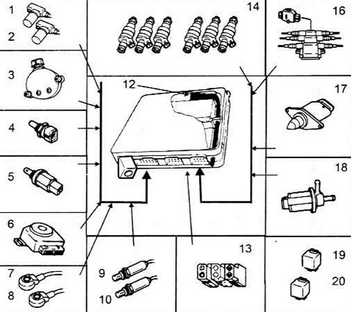
Basic Elements of MPI and MPFI
1 Battery
2 Gas cable
4 Brake fluid reservoir
5 Expansion tank cap
6 Fuse box
7 Power steering pump reservoir
8 Windscreen washer reservoir
9 ABS control unit
10 Oil dipstick
11 Block cover
13 Oil filler neck
14 Casing
16 Air filter cover
17 Magnetic valve
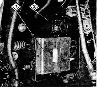
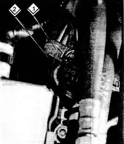
1 Lambda probe relay
2 Electronic control unit
The MPI and MPFI systems are multi-point fuel injection systems that share a common control unit with the ignition system. The difference between the systems is that the MPI system has a switchable intake manifold consisting of two parts, and the MPFI system has a non-switchable intake manifold consisting of three parts. In addition, the MPFI system does not require an air mass meter.
The principle of operation of the system is that fuel from the tank is supplied by an electric fuel pump into a ring pipeline, then through individually controlled injectors it is injected into the intake manifold in front of the intake valves.
The ignition and injection system control unit, based on data received from the sensors, regulates the injection time and, consequently, the amount of fuel injected.
Control unit sensors
Inductive ignition timing sensor - is required when starting the engine to determine the top dead center of the third cylinder. The sensor is usually installed on the left side of the engine crankcase.
Coolant temperature sensor - the sensor signal serves as a factor for adjusting the injection moment and time when the engine is not warmed up. The sensor is installed in the coolant line of both cylinder heads.
Hall sensor - the sensor signal is required when starting the engine in order to determine the top dead center of the third cylinder along with other sensors. The sensor is installed on the left cylinder head.
Idle switch and throttle potentiometer - they transmit information about the throttle position to the control unit, thereby regulating the moment of shutting off the supply. These elements are installed in a common housing on the throttle block.
Two lambda sensors - they measure the oxygen content in the exhaust gases and inform the control unit about it. The control unit, based on the information received, regulates the ratio of the amount of injected fuel and air. The sensors are installed in the corresponding exhaust manifolds of each cylinder head.
Idle speed stabilization valves (not all engines). It regulates the amount of air passing bypassing the throttle valve at idle speed. Thus, a specified number of idle revolutions is maintained. The valve is installed on the intake manifold
The intake manifold is designed so that the intake air, depending on the engine speed, can be directed by the valve either along the long path or along the short path. The engine torque depends on this.
Exhaust gas feedback system - it is necessary to reduce the content of harmful substances in the exhaust gases and consists of two valves (mechanical and electrical).
The original text is available on the website: AUDImanual.ru