
Table of contents: Throttle control unit ↓ Fuel pressure regulator ↓ Injectors ↓ Incoming air temperature sensor ↓ Coolant temperature sensor ↓ Air flow meter ↓
Although there is little work that can be done on the injection system, it is worth briefly mentioning the main parts and how they work in the system.
the "brain" of the injection system and the ignition system connected to it is the control unit. It is located in the electronic unit on the left rear in the engine compartment (in a space that can also be called a casing). If a turbocharger is installed, then there is also an altitude sensor, i.e. a device that regulates the boost pressure when driving at high altitude, for example, in the mountains. In the car itself, the control unit is recognized by its black case, since it is covered with a lid. Under the cover (1) of the electronic unit is the electronic control unit.
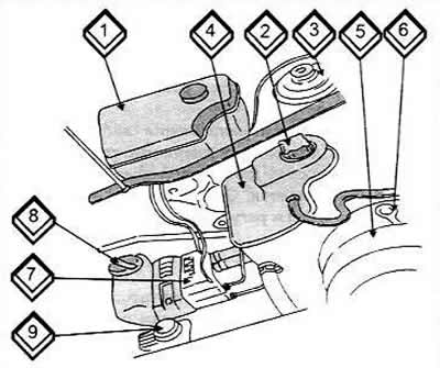
1 Electronic block
2 Expansion tank cap
3 Brake fluid reservoir
4 Expansion tank of the cooling system
5 Collector
6 Oil dipstick
7 ABS control unit
8 Windscreen washer reservoir
9 Power steering pump reservoir
The control unit receives the following information via the multi-pin plug.
- From the starter terminal 50 about the beginning and end of the starting process.
- The potentiometer on the throttle valve gives the instantaneous throttle position.
- The Hall sensor of the ignition system, among other things, provides information on the engine speed. The lambda probe in the catalytic converter informs about the content of residual oxygen in the exhaust gases. The air flow meter determines the amount of incoming air.
Turbocharged engines are equipped with an inlet air temperature sensor, which continuously informs the control unit about the inlet air temperature.
The coolant temperature sensor is located in the coolant pipe behind the cylinder head and supplies the control unit with information about the coolant temperature at a given moment.
A knock sensor or two knock sensors are screwed into the cylinder block. They regulate knock combustion and accordingly regulate the ignition timing.
Thanks to the constant receipt of the above-mentioned data on the number of revolutions, load and engine temperature, the control unit determines the duration of injection, i.e. the time of opening of the injectors and precisely doses the amount of fuel injected. The control unit has so-called ranges built in (databases), which cover all possible engine operating conditions and, based on them, precisely select the optimal fuel doses and ignition timing. When the temperature of the incoming air or coolant changes, the necessary adjustments are made.
Before briefly describing the operation of individual parts, we will briefly mention the general principles of operation of the system under various operating conditions.
At a "cold" start (starting a cold engine)
The presence of the throttle control unit allows additional air to enter the engine because the coolant temperature sensor tells the control unit that the engine is cold. The injectors open for a longer time and inject more fuel (enriching the mixture).
When warming up
The control unit is informed about the gradual heating of the coolant. The built-in idle speed stabilization valve closes and the duration of the injector opening returns to the nominal value.
At idle
The control unit detects the idle speed. This is reported by the potentiometer on the throttle valve of the throttle control unit to the air flow meter of the control unit ("master"). When the speed decreases, the ignition timing changes. More air can flow through the throttle control unit, which increases the amount of fuel injected.
During normal engine operation
The position of the throttle valve and the air flow meter data on the amount of air flowing through determine the duration of the injector opening and, subsequently, the engine operation.
Now we can talk in more detail about the details of the system already mentioned above.
Throttle control unit
This device contains various parts. The first is the throttle valve. It is connected to the gas pedal via the throttle lever and cable. The figure shows the position of the throttle valve with the air duct (hose) removed. In accordance with the position of the gas, the cross-section of the opening for the supply of the working mixture increases or decreases. At full load, it opens completely. In some engines (as a rule, smaller volume), the throttle valve works on the same principle, but the installation methods differ.
Throttle body assembly
1. Throttle lever
2. Connecting socket for plug
3. Throttle control unit
4. Throttle valve (closed)
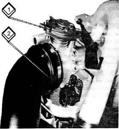
Throttle body connections
1. Connecting socket for plug
2. Throttle lever
The control unit has a throttle potentiometer. It "monitors" the throttle position under all conditions and reports this to the control unit. Based on the information received, stabilization of the idle mode, shutdown during coasting and enrichment in full load mode are determined.
The idle speed stabilization valve equalizes the idle speed at maximum steering wheel rotation, when the air conditioning system is switched on, or when an automatic transmission is installed, when additional air can flow behind the throttle valve. This additional air is monitored by the air flow meter so that more fuel can flow into the engine. The engine can run slightly faster, so that the additional engine power consumed by the power steering, air conditioning system, or automatic transmission is compensated.
Fuel pressure regulator
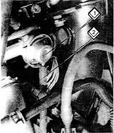
The fuel pressure regulator (1) is usually located before the fuel distributor and regulates the pressure of the fuel supplied to the injectors. Since it is connected by a hose (2) to the throttle body, it is controlled by the vacuum in the intake manifold.
When the vacuum increases (for example, at idle), the pressure is maintained low. If the engine speed increases, the vacuum decreases. This means that the fuel pressure is increased by the regulator.
Injectors
With each revolution of the crankshaft, fuel is injected into the intake port in front of the intake valve (or valves) corresponding cylinder The opening of the injector is determined by the electronic control unit.
Incoming air temperature sensor
It is installed only on turbocharged engines. The sensor reports the temperature of the air under pressure coming from the turbocharger, which is processed in the control unit. This compensates for the increase in temperature from the supercharger.
Coolant temperature sensor
The coolant temperature determines many engine functions, such as enrichment when starting a cold engine, warming up, acceleration and fuel cut-off when coasting. The temperature is transmitted to the control unit as a resistance value. This determines the correct injection duration, which is extended accordingly when the engine is cold.
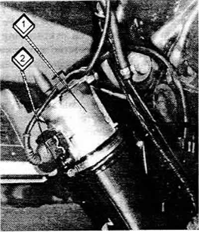
Air flow meter
The air flow meter (1) together with the connecting plug (2) is located next to the air filter.
In a turbocharged engine, the flow meter is not visible because it is located inside the air filter housing. In the flow of incoming air there is a small plate that is heated by an electric current. If the amount of incoming air increases, the plate is cooled accordingly. This cooling causes a change in electrical resistance, which is communicated to the control unit.