Repair Chevrolet Repair Toyota Repair Honda Repair AvtoVAZ Repair Mercedes-Benz Repair BMW Repair Opel
Home  |  Contacts  |  Sitemap  |    
English Русский
Български
Беларускі
Український
Српски
Hrvatski
Română
Polski
Slovenský
Magyar
AudiManual.ru


  • AUDI 80
  • AUDI 100
  • AUDI A3
  • AUDI A4
  • AUDI A6
  • AUDI A8
  • AUDI Q
  • OTHER
  • ARTICLES
C4 (1990-1994) C4 (1990-1994, petrol) C3 (1982-1990) C3 (1982-1990, petrol) C3 (1982-1990, diesel)

Search for faulty components of the KE-III-Jetronic injection system (Audi 100 C4)

  • Home
  • Audi 100
  • C4 (1990-1994)
  • Power unit
  • Fuel system (gasoline)
  • Search for faulty components of the KE-III-Jetronic injection system
            0
Table of contents: Checking the injectors ↓ Checking the cold start assist valve ↓ Checking the fuel dispenser ↓ Checking the air flow meter ↓
If you have any doubts about the serviceability of any part, you can check it.

Checking the injectors


Switch off the ignition as described in the relevant section.

To check whether fuel is being supplied to the injector, loosen the fuel line mounting bolt on the cold start valve.

Prepare a rag and ask an assistant to turn the starter.

If fuel is leaking, you need to check the injector itself.

Remove the injector (see further in this section).

To do this on some five-cylinder engines, it is necessary to remove the upper part of the intake manifold.

Keep a container or rag ready to collect any spilled fuel.

Remove the large air hose between the mixture regulator and the throttle body to gain access to the air flow meter pickup plate.

In the central distribution device, disconnect the fuel pump relay and short-circuit the contacts on the block with a piece of wire. The fuel pump should work.

The measuring plate in the dispenser should be slightly raised by hand. The injector should then create a conical jet. If this is not the case: raise the measuring plate as far as it will go. Repeat the test.

In a similar way, the difference in the amount of fuel injected between individual cylinders can be checked.

Each of the injectors should be lowered into its own measuring cup (there should be four or five of them), without kinking the high-pressure fuel lines.


Raise the measuring plate by approximately 2 cm.

The assistant should keep the above mentioned wire jumper inserted until 2 cm³ of fuel has been poured into the first cup.

Compare the amount of fuel in different cups. The difference should not exceed 3 cm³.

If the deviation is greater, swap the injectors with the minimum and maximum amount of fuel injected. Repeat the measurement.

If, with the replacement of injectors, the deviations in the amount of fuel also change places, then the injector with excessive deviation must be replaced.

If, upon re-checking, you get the same results, then it is possible that the fuel line leading to the injector is narrowed or the fuel dispenser is faulty.

Checking the tightness of the injectors: if you turn off the fuel pump after two minutes of operation (pull out the jumper), there should be no dripping from the injectors.

The procedure for installing injectors is described below.

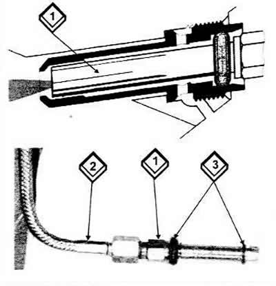
The injector (1) has been removed together with the sealing rings (3) and the connected high-pressure fuel line (2). The injector is shown here with two sealing rings. The picture on the right shows the operating principle of the air-flushed injector. By supplying additional air (indicated in a lighter color) better fuel atomization is achieved (darker color) in idle mode.

The injector (1) has been removed together with the sealing rings (3) and the connected…


Checking the cold start assist valve


The check is carried out when the engine has cooled down.

Turn off the ignition.

Unscrew the cold start valve, leaving the plug and fuel line connected.

Lower the valve into the vessel and ask an assistant to turn the engine.

The valve should produce a conical shaped jet of fuel.

The injection duration depends on the engine temperature. At 0°C, the injection duration ranges from 3 to 7 ½ seconds, at 10°C — from 2 to 6 seconds, at 20°C — from 1 to 4 seconds. After injection, turn off the ignition.

Dry the valve by blotting it. No fuel should come out within a minute.

Checking the fuel dispenser


Let the engine run for about one minute.

Remove the air filter cover and filter element

From below, through the inlet shaft of the measuring plate, press the adjustment lever all the way up. The same resistance should be felt along the entire length of the stroke.

There should be no resistance when quickly pulling the measuring plate back. If there is, the air flow meter must be replaced.

If the measuring plate moves up with difficulty, but moves down easily, then the distribution piston is "stuck" in the dispenser. Replace the fuel dispenser.

Checking the air flow meter


Warm up the engine, or let the warmed up engine run for about 1 minute before checking.

Remove the air intake hose between the mixture regulator and the intake manifold by loosening the clamping straps.

Check the measuring plate: the measuring plate should be 1.9 mm below the top edge, in extreme cases 3 mm below.


If the measuring plate is not positioned correctly, it must be raised by bending the retaining wire clip at the bottom of the air flow meter shaft to correct its position. The flat spring must not be bent under any circumstances.

Check if the measuring plate touches the wall.

If so, you will need to loosen the center mounting bolt and re-center the plate.

The original article is available on the online resource Audimanual.ru
The article was checked by auto expert Georgy Rodionov
This article is available at russian, bulgarian, belarusian, ukrainian, serbian, croatian, romanian, polish, slovak, hungarian

Share information:
Previous articles
Audi 100 C4: Fuel system (gasoline)
Next articles

Self-diagnosis of faults in the KE-III-Jetronic injection system
Functioning of the KE-III-Jetronic fuel injection system
General structure of the KE-III-Jetronic fuel injection system
Adjusting the idle speed and CO content of the Monomotronic…
General description and safety precautions when working with the…
Operation of the KE-III-Jetronic injection system
Possible malfunctions of the KE-III-Jetronic injection system
Work on the KE-III-Jetronic injection system


Similar articles on other Audi car models:
Electrical connection diagram of the fuel injection system… Audi 80 B3 (1986-1991, petrol)
Fuel injection system device (petrol) Audi A3 Type 8L (1996-2003)
Injection system components Audi A4 B5 (1994-2001, petrol)
Motronic/Jetronic fuel injection system components Audi A6 C4 (1994-1997)
General information about the ignition and fuel injection system Audi A8 D2 (1994-2002)
Injection system Audi Q5 Type 8R (2008-2017)
General information about the fuel injection system Audi A2 (1999-2005)
Link to this page in different formats


Visitor comments

No comments yet


How much will 34 + 47 =


100(C4, 1990-1994) 
  • General information
  • User manual
  • Power unit
  • Engine repair
  • Ignition system
  • Fuel system (gasoline)
  • Fuel system (diesel)
  • Lubrication system
  • Cooling system
  • Exhaust system
  • Transmission
  • Clutch
  • Car gearbox
  • Drive shafts
  • Chassis
  • Car suspension
  • Steering
  • Wheels and tires
  • Brake system
  • Body
  • Ventilation and heating
  • Body repair
  • Electrical equipment
  • Power devices
  • Lighting and appliances
  • Electrical circuits
 
100(C4, 1990-1994, petrol) 
  • General information
  • Operation and maintenance
  • Power unit
  • Engine repair
  • Exhaust system
  • Cooling system
  • Supply system
  • Air filter
  • Mono-Motronic injection system
  • Digifant injection system
  • KE-III-Jetronic and KE-Motronic
  • MPI and MPFI injection system
  • Transmission
  • Clutch
  • Car gearbox
  • Chassis
  • Suspension and steering
  • Brake system
  • Wheels and tires
  • Body
  • Exterior
  • Interior
  • Electrical equipment
  • Fuses and relays
  • Power devices
  • Ignition system
  • Lighting and signaling
  • Equipment and devices
  • Electrical circuits
 
100(C3, 1982-1990) 
  • General information
  • User manual
  • Maintenance
  • Specifications
  • Power unit
  • Engines 4-cylinder
  • Engines 5-cylinder
  • Diesel engine
  • Cooling system
  • Power system (carburetor)
  • Power system (injector)
  • Fuel system (diesel)
  • Transistor ignition system
  • Electronic ignition system
  • Transmission
  • Clutch
  • 4 speed gearbox 014
  • 5 speed gearbox 013 and 093
  • 5 speed gearbox 016 and 012
  • Shift mechanism KP 016
  • Automatic transmission
  • Front wheel drive
  • Chassis
  • Front suspension
  • Rear suspension
  • Steering
  • Brake system
  • Body
  • Body elements
  • Electrical equipment
  • Lighting and appliances
  • Power devices
  • Electrical circuits
 
100(C3, 1982-1990, petrol) 
  • General information
  • Maintenance and operation
  • 4 cylinder engine
  • Engine repair
  • Cooling and lubrication system
  • Supply system
  • Ignition system
  • 5 cylinder engine
  • Engine repair
  • Cooling and lubrication system
  • Supply system
  • Ignition system
  • Transmission
  • Clutch and drive shafts
  • 4 speed gearbox 014
  • 5 speed gearbox 013 and 093
  • 5 speed gearbox 016 and 012
  • Automatic gearbox
  • Chassis
  • Steering
  • Front suspension
  • Rear suspension
  • Brake system
  • Body
  • Body elements
  • Doors, locks and windows
  • Body repair
  • Electrical equipment
  • Equipment and devices
  • Power devices
  • Electrical circuits
 
100(C3, 1982-1990, diesel) 
  • General information
  • User manual
  • Maintenance
  • Troubleshooting
  • Power unit
  • Engine in a car
  • Engine removed
  • Cooling system
  • Fuel system
  • Exhaust system
  • Starting and charging
  • Preheating
  • Transmission
  • Clutch
  • Mechanical gearbox
  • Automatic gearbox
  • Drive shafts
  • Chassis
  • Brake system
  • Suspension
  • Steering
  • Body
  • Exterior
  • Interior
  • Electrical equipment
  • Equipment and devices
  • Electrical circuits
 
AudiManual.ru © 2017-2026 · Mobile version · Feedback · Sitemap: EN BG BY UA RS HR RO PL SK HU · Site search · News and articles
80 B2 · 80 B3 petrol · 80 B3 · 80 B4 · 100 C3 diesel · 100 C3 petrol · 100 C3 · 100 C4 petrol · 100 C4 · A3 Type 8L · A4 B5 petrol · A4 B5 · A4 B6 petrol · A4 B6 · A4 B7 · A4 B8 · A6 C4 · A6 C5 · A6 C5 Allroad · A8 D2 · Q5 Type 8R · Q7 Typ 4L · Audi A2 ·
This site uses cookies 🍪. Click the button to accept this fact.