
Table of contents: Distinctive features of the… ↓ Diaphragm pressure regulator ↓ Potentiometer ↓ Fuel cut-off valve ↓
There are various modifications of injection systems based on the principle of the K-Jetronic system and installed on various engines.
The KE-III-Jetronic system takes electronics one step further. Together with the fully electronic ignition system "VEZ", it forms a complete engine management system. Although each system uses its own control units, data is exchanged between them. In addition, these systems often receive information from the same sensors. A diagnostic system with memory is used to search for faults.
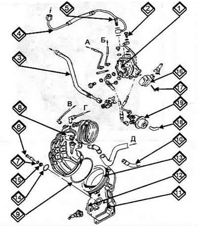
Elements of the KE-III-Jetronic injection system
1 Fuel distributor
2 Cork (pressure measurement point)
3 Fuel return hose.
4 Pipe from the fuel tank
5 Hollow bolt
6 Adjusting rod
7 Seal
8 Valve of the activated carbon tank (magnetic)
9 Grid
10 Crankcase ventilation sludge
11 Air quantity meter
12 Potentiometer
13 Protective plug
14 Seal
15 Adjusting rod stop
16 Pressure sensor
17 Anti-magnetic bolt
18 Ventilation pipe (to the air filter)
19 Pressure regulator
A. To the injector
B. To cold start valve
B. To the container with activated carbon
G To the throttle body
D. To the idle speed stabilization channel
Distinctive features of the KE-III-Jetronic system
Pressure regulator
It replaces the preheat regulator, since it does not change the pressure acting on the control piston, but controls the pressure in the grooves (slots) for mixing the fuel. As a result, the amount of fuel can vary in the proportion of 1:2.5, depending on the current passing through the coil.
Electronic control unit
Via the multi-pin plug, the control unit receives information from the following components:
- From the starter about the beginning and end of the engine starting cycle.
- From the Hall sensor in the ignition distributor about engine speed.
- From the lambda probe in the exhaust manifold about the amount of oxygen in the exhaust gases.
- From the potentiometer on the air flow meter about the position of the measuring plate.
- From the temperature sensor about the coolant temperature. In accordance with the operating conditions, the signals are processed into a current of the corresponding magnitude and transmitted further to the regulator coil.
- The information for the KE-III-Jetronic control unit is even more extensive. This unit receives additional data from the ignition system from the altitude sensor (atmospheric pressure) and from the automatic transmission. As a rule, it is located together with the height sensor on the right in the front passenger footwell.
Diaphragm pressure regulator
It is located next to the mixture regulator and performs the same task as the pressure regulator of the K-Jetronic system. The working pressure of the KE-III-Jetronic system is 6.1-6.5 bar.
Potentiometer
It detects the position of the air flow meter measuring plate and transmits this information as a voltage signal further to the control unit.
Fuel cut-off valve
The coasting fuel cut-off valve (2) is located on the air filter housing (1) near the mixture regulator (3). The diagram shows the operating principle of the fuel cut-off valve.
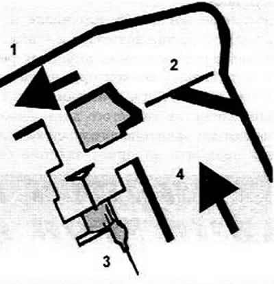
1 To the engine
2 Air flow meter
3 Fuel cut-off valve
4 Incoming air
Material republished from the website AUDIMANUAL.RU