
Table of contents: 2.5L direct injection engine ↓ 1.9L direct injection engine ↓ Pump-injector unit ↓
The fuel system of a diesel engine is controlled by an electronic engine management system. It has the following advantages:
- Self-diagnosis of the engine management system allows for quick troubleshooting.
- Precise dosing of the injected fuel quantity ensures a reduction in the content of harmful substances in exhaust gases and low fuel consumption.
- Idle speed and rev limiting are controlled automatically.
When a diesel engine is running, clean air is sucked into its cylinders and compressed to high pressure. The air temperature rises to 700°C, which exceeds the ignition temperature of diesel fuel. The fuel is injected into the cylinder a little ahead of the ignition temperature and ignites. Thus, spark plugs are not used to ignite the fuel.
Air is sucked into the engine or supplied by the turbocharger and passes through the air filter. The turbocharger compresses the air, which then enters the intercooler, where it is cooled after being heated by compression in the turbocharger. The cooling helps to better fill the cylinders with forced air, which in turn increases the torque and power of the engine.
To reduce the proportion of harmful substances in the exhaust gases, diesel engines have a diesel oxidation catalytic converter. At the same time, the recirculation system ensures a significant reduction in the content of nitrogen oxides in the exhaust gases. This is achieved by feeding the exhaust gases to the air sucked in by the engine, which reduces the oxygen concentration in the air entering the engine cylinders. This leads to a delay in ignition and a lower combustion temperature, which ultimately reduces the formation of NOx. The process of recirculation of exhaust gases must, however, be precisely dosed, since otherwise the soot content in the exhaust gases increases. For this purpose, the amount of sucked air is determined by a meter, which allows the electronic unit to control the recirculation process.
Fuel is injected directly into the combustion chamber.
The piston bottoms contain vortex chambers, providing a swirl of the fuel entering the combustion chambers.
The cold engine warm-up is controlled by the engine control unit. When the engine is cold, the injection timing is shifted by the control unit. The engine control unit, in turn, controls the glow plugs. Glow plugs are installed in each cylinder and are switched on before starting the engine, operate while the engine is cranked by the starter and for some time after starting the engine. Spark plugs make starting a cold engine much easier. After turning on the ignition, a lamp lights up on the dashboard (refer to Chapter Controls and safe operation techniques), signaling the activation of the glow plugs. As soon as the lamp goes out, you can start the engine. If the ambient temperature is very low, the glow plugs continue to work for some time after the engine has started. This ensures stable engine operation and a reduction in harmful impurities in the exhaust gases.
Due to the high starting properties of the direct injection engine in a cold state, pre-heating is only required at temperatures below -10°C.
Fuel passes through the fuel filter. In the filter, fuel is separated from water and contaminants. Therefore, it is important to remove water from the fuel and replace the filter element in a timely manner.
2.5L direct injection engine
Location of injection system components in the 2.5L diesel engine compartment
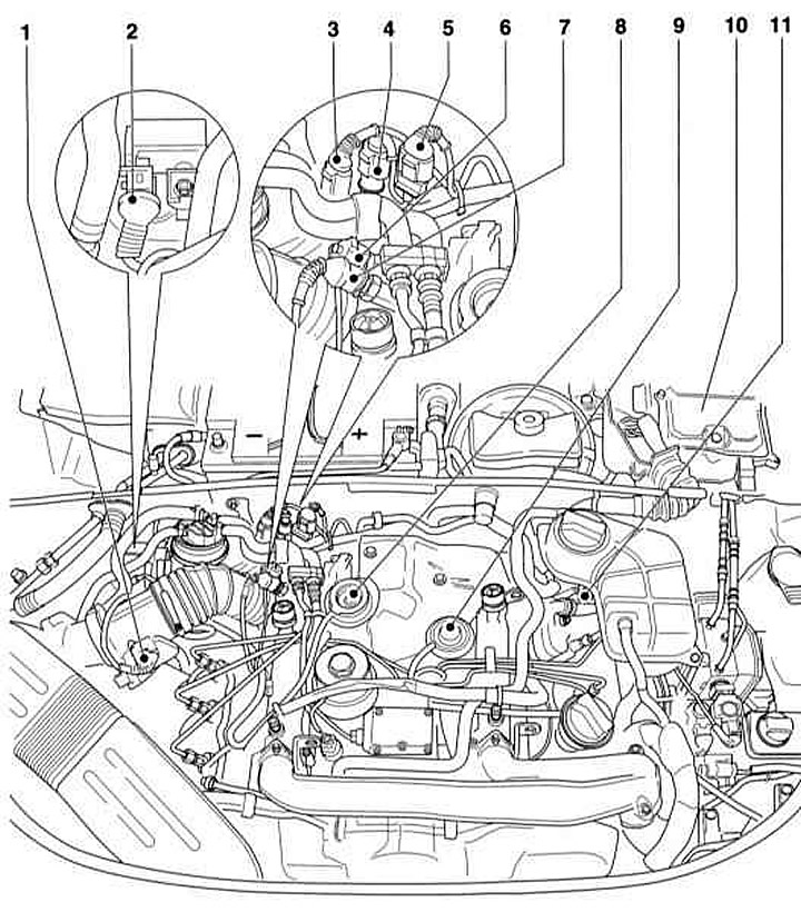
- 1 - Mass meter with intake air temperature sensor in the upper part of the air filter housing
- 2 — Solenoid valve for limiting the boost pressure
- 3 — Terminal 50 connector between the starter switch and the starter
- 4 — 2-pin connector of the needle stroke sensor. Not available on the BCZ engine
- 5 - 3-pin engine speed sensor connector.
- 6 — Oil pressure sensor
- 7 — Oil temperature sensor
- 8 — Vacuum drive for adjusting the inflation pressure
- 9 — Mechanical exhaust gas recirculation valve
- 10 - Electronics box in the water collection compartment with:
- direct injection system control unit, with height sensor
- aT control unit
- direct injection system relay
- glow plug relay
- glow plug fuse
- fuel pump relay
- 11 — Engine speed sensor
Fuel is sucked in by the distribution fuel injection pump from the fuel tank.
The high-pressure fuel pump creates a pressure of about 900 atm and injects fuel through multi-jet nozzles in two stages, in accordance with the ignition order. First, a preliminary injection of a small volume of fuel is performed, which creates the necessary conditions for the subsequent injection of the main volume of fuel. This process ensures a softer and less noisy combustion of fuel, similar to what happens with swirl-chamber injection.
The high-pressure fuel pump does not require maintenance. All moving parts of the pump are lubricated with diesel fuel. The high-pressure fuel pump is driven from the engine crankshaft by a toothed belt.
1.9L direct injection engine
Location of injection system components in the 1.9L diesel engine compartment
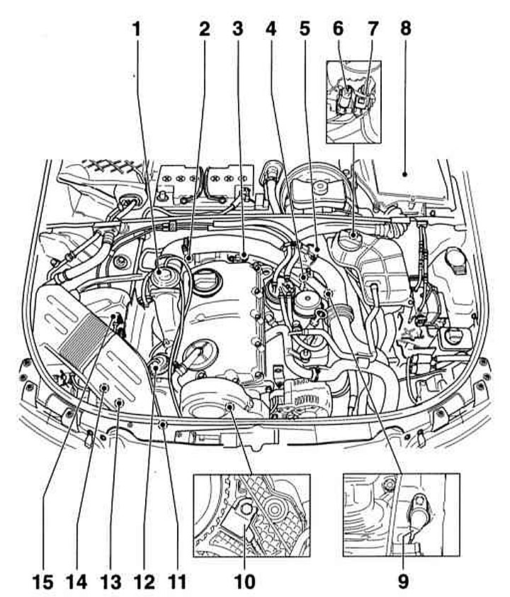
- 1 — Mechanical exhaust gas recirculation valve with intake manifold flap
- 2 — Coolant temperature sensor
- 3 — Pump-injector unit connector
- 4 — Fuel temperature sensor
- 5 — Suction pressure sensor with intake air temperature sensor
- 6 — Engine speed sensor connector
- 7 — Camshaft position Hall sensor connector
- 8 — Electronic box in the water collection compartment. Direct injection system control unit with height sensor
- 9 — Engine speed sensor
- 10 — Hall sensor of camshaft position
- 11 — Boost pressure limiting solenoid valve
- 12 — Vacuum actuator for boost pressure limitation
- 13 — Intake manifold flap switching valve
- 14 — Valve 1 of the exhaust gas recirculation system
- 15 — Air mass meter
Here, the injection is carried out by means of a "pump-nozzle" system (illustration below). Unlike the previous injection system, where the fuel is compressed by one injection pump for all injectors, the pump-injector system has its own injection pump for each cylinder.
Thus, the high-pressure fuel pump, control valve and injector are combined in one block.
Pump-injector unit
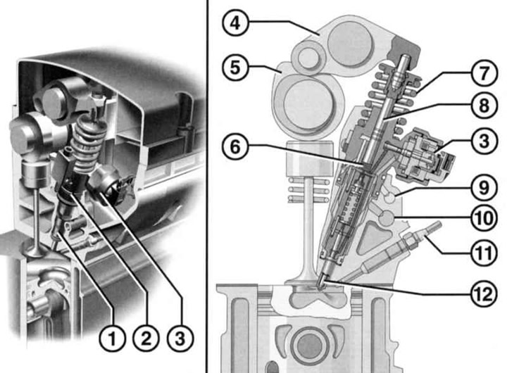
- 1 — Nozzle
- 2 - Pressure pump
- 3 — Control unit (electromagnetic valve)
- 4 - Roller lever
- 5 — Injection cam
- 6 - High pressure cavity
- 7 — Piston spring
- 8 — Pump piston
- 9 — Fuel return
- 10 — Fuel supply
- 11 - Glow plug
- 12 — Injector needle
Diesel fuel is supplied by an electric fuel pump located in the tank, as well as a mechanical fuel pump that supplies fuel to the pump-injector unit. The mechanical fuel pump, together with the vacuum pump, is fixed to the cylinder head and is driven directly by the camshaft. The four fuel pumps of the pump-injector unit are driven by an additional cam located on the camshaft, via a roller lever. The volume of injected fuel is regulated by the engine control unit via electromagnetic valves.
Due to the high compression pressure in the pump-injector unit, the fuel heats up strongly, which has a negative effect on the operation of the fuel reserve sensor in the tank. To cool the fuel, there is a special refrigerator in the return pipeline.
Before the fuel enters the fuel pump, it passes through the fuel filter. There, water and impurities are separated from the fuel. It is important to pay attention to the importance of servicing the fuel filter.
Caution: When working on the fuel system, safety precautions and special cleanliness are required, refer to Section General information and safety precautions.
[The article is a reprint of material from «AUDIMANUAL.ru»]