
Table of contents: Safety precautions when working with… ↓ Notes on checking the engine… ↓ Operation of the petrol engine… ↓ Location of film conductor 1 in the… ↓ Engine control sensors and actuators ↓ Fuel injection system checks -… ↓
Simos Engine Management System Components Location. 1.6L Engines
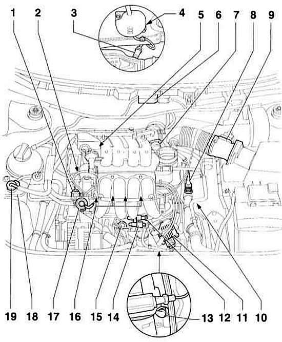
- 1 connector. For Hall sensor (black)
- 2 Hall sensor. Under the upper timing belt cover
- 3 oxygen sensor, 50 N. Position at AT: in the exhaust manifold
- 4 connector. For oxygen sensor, on the lower side of the car on the right
- 5 Intake manifold switching valve
- 6 Simos control device
- 7 throttle control unit
- 8 coolant temperature sensor
- 9 Air mass meter. With intake air temperature sensor
- 10 ground connection at manual transmission
- 11 ignition coils. With output power stage
- 12 connector. For knock sensor
- 13 engine speed sensor
- 14 connector. For engine speed sensor (black)
- 15 knock sensor
- 16 injectors
- 17 fuel pressure regulator
- 18 adsorber
- 19 Evaporative..
Motronic Engine Management System Components Location. 1.8L Engine (125 HP)
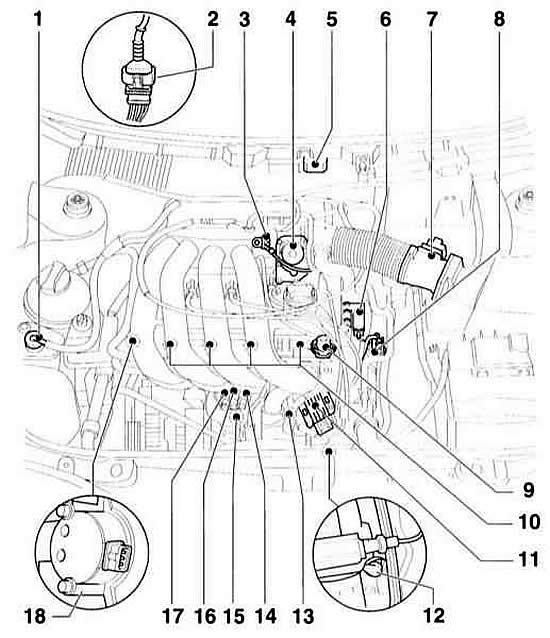
- 1 electromagnetic valve for the adsorber
- 2 connector. For oxygen sensor (black)
- 3 intake air temperature sensor
- 4 throttle control unit
- 5 Motronic control unit
- 6 camshaft adjustment valve
- 7 air mass meter
- 8 coolant temperature sensor
- 9 fuel pressure regulator
- 10 injectors
- 11 ignition coils, output stage
- 12 engine speed sensor
- 13 knock sensor 2
- 14 connector. For knock sensor 2.
- 15 knock sensor 1
- 16 connector. For engine speed sensor.
- 17 connector. For knock sensor 1.
- 18 Hall sensor
Note: From 8/97 onwards, an adjustable intake pipe with changeover valve is additionally installed.
The electronic engine management system regulates the amount of fuel supplied to the cylinders and controls the ignition process. Gasoline engines of the AUDI A3 use various control systems.
The electronic engine management system provides the following capabilities:
- Precise fuel dosing in any operating mode, which ensures low fuel consumption with high power.
- Reduction of the content of harmful substances in exhaust gases thanks to precise fuel dosing and the use of a catalytic converter.
- Self-diagnosis of the engine management system, which provides the ability to quickly find a fault. The engine management system has a fault memory. If a defect is detected during operation, it is recorded in the device's memory. If there are faults in the engine, it is possible to print a list of faults on the printer, allowing you to identify and eliminate the defect yourself.
The engine control unit is a high-speed microprocessor. It determines the optimal injection time and the amount of fuel injected. At the same time, the control unit is coordinated with other vehicle systems, such as the manual transmission control system or theft protection system.
The engine control system elements maintain their high performance for a long time and require virtually no maintenance. Only the air filter and spark plugs require replacement during maintenance. Serious adjustment and repair work requires the use of complex diagnostic devices. They can only be carried out at a service station.
Adjustment of idle speed and CO concentration is not required as part of maintenance.
Safety precautions when working with the engine management system/petrol engine
The fuel system is under pressure! When opening the system, fuel may be released. Therefore, any leaked fuel must be wiped with a rag. Gasoline vapors are poisonous and flammable. Use safety glasses. Ensure good ventilation of the workplace. Have a fire extinguisher at hand.
To avoid injury to people and/or damage to the injection and ignition system, the following must be observed:
- Do not touch or disconnect spark plug wires while the engine is running or the starter is engaged.
- Disconnect and connect injection system pipes and ignition wires, as well as electrical wires of measuring devices only with the ignition switched off.
- People with a pacemaker should not work on the electronic ignition system.
- When checking compression, fuel injection is not allowed.
Warning: When working on the injection system, general safety and cleanliness rules must be observed.
Notes on checking the engine management system
- To troubleshoot, first of all, it is necessary to retrieve the readings from the fault memory and check the vacuum connections for leaks.
- For reliable operation of all electrical elements of the system, a voltage of at least 11.5 V is required.
- If after troubleshooting, repairs or checking parts it starts only for a short time and then stops, the reason may be that the anti-theft system is blocked. To do this, it is necessary to interrogate the fault memory and, if necessary, adjust the control unit.
Operation of the petrol engine injection system
Fuel is sucked from the fuel tank by an electric fuel pump and fed through a fuel filter located on the floor of the car to the injectors. A pressure regulator maintains constant pressure in the fuel system.
The fuel is injected in portions into the respective intake manifold directly in front of the engine intake valves via electrically controlled injectors. The engine control unit controls the injection duration and thus the amount of fuel injected.
Air drawn into the engine passes through the air filter, enters through the throttle valve and the intake pipe to the intake valves.
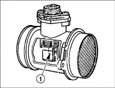
The mass of the sucked-in air determines the amount of fuel injected. The mass of the sucked-in air is measured by a special meter. The meter housing contains a thin, electrically heated sensing plate –1–, which is cooled by the air flow passing through it. To maintain a constant temperature of the sensing plate, the current value changes in accordance with the mass of the sucked-in air. The current value indicates to the control unit the degree of engine load and thus regulates the amount of fuel injected.
Location of film conductor 1 in the air mass meter
Information from various sensors and commands to actuators ensure optimal engine operation under various operating conditions. If sensors fail, the control unit switches to an emergency program to prevent engine damage and ensure the possibility of further vehicle movement. Sensor failure does not necessarily have a negative impact on engine operation. However, when closely monitoring the composition of exhaust gases, it is necessary to read the fault memory of the engine management system.
Engine control sensors and actuators
Throttle valve is located in the central control unit, where information from various sensors is concentrated. The main task of the control unit is to stabilize the idle mode under all engine operating modes and load conditions. The idle switch transmits information about the idle position of the throttle valve to the control unit. The control unit opens or closes the throttle valve via the electric motor, thus regulating the idle speed.
Coolant temperature sensor and intake air temperature sensor transmit information about the current temperature value to the control unit based on the change in their electrical resistance value. As the temperature increases, the resistance decreases.
The fuel tank ventilation system consists of adsorber and electromagnetic valve. The adsorber accumulates gasoline vapors that form in the tank as a result of heating the fuel. When the engine is running, gasoline vapors are sucked out of the adsorber and fed to the engine.
Oxygen sensor measures the oxygen content in the exhaust gases and transmits a corresponding signal to the engine control unit.
Knock sensor serves to determine the optimal ignition moment. In case of ignition faults, the fuel supply to the corresponding cylinder is stopped.
1.8L/125hp engines with 8/97, 1.6L engines have adjustable intake manifold, which changes the parameters of the intake tract depending on the engine speed. For this purpose, a flap with a pneumatic drive is installed in the intake manifold. A long manifold at low engine speeds ensures good filling of the cylinders and thus high torque due to the resonance effect. At high engine speeds, the intake manifold is shortened, which ensures more complete use of the engine's power potential.
Engines 1.8 l/125 hp: To obtain optimum engine power and torque over a wide rev range, there is mechanism for regulating the opening and closing moment of intake valves depending on the number of revolutions. Usually the opening and closing time is determined by the configuration of the camshaft. To provide variable adjustment of the cams, the intake and exhaust camshafts are connected to each other by a chain. The hydraulic adjustment mechanism, depending on the engine speed, shifts the turning point of the chain in the branch of the camshaft gear connection. Due to this, the phases of the intake valves are shifted in relation to the exhaust valves. To increase torque in the range from low to medium speeds, the adjustment mechanism is activated, and the intake camshaft opens and closes the valves earlier.
Fuel injection system checks - general information
In the fuel injection system, you can only check the main electrical circuits yourself.
If the engine is not running normally, first check the condition of the electrical wiring and connectors. Check the condition of the air filter element, as well as the condition and interelectrode gap of the spark plugs. Check the crankcase ventilation hoses for patency and the adjustment of the accelerator cable. If the engine still runs unsteadily, check the compression in the engine cylinders.
If you suspect that the injector is not working properly, clean it.
If the engine still runs rough, check the ignition system components.
If the fault is still present, check the integrity of the fuses and the condition of the electrical connectors and wiring. There should be no melted contacts, moisture, corrosion, dirt or other damage on the electrical connectors.
After performing an independent check, contact a specialized AUDI station for diagnostics of the fuel injection system using special equipment.