
Location of the fuel system components in the TDI engine compartment
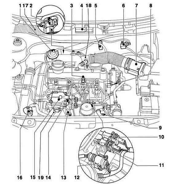
- 1 exhaust gas recirculation valve
- 2 suction flap bypass valve
- 3 nozzle with needle displacement sensor
- 4 control device
For direct fuel injection system. The height sensor is built into the control unit.
- 5 E/m EGR vacuum control valve
- 6 solenoid valve
To limit the supply air pressure.
- 7 air mass meter
- 8 coolant temperature sensor
- 9 engine speed sensor
- 10 plug connection. Needle displacement sensor.
- 11plug connection for engine speed sensor
- 12 plug connection injection pump
For coolant temperature sensor, quantity adjuster, control flap travel sensor, fuel cut-off valve and injection start valve.
- 13 fuel injection start valve, d / in oil pressure
- 14 fuel cut-off valve
- 15 executive body for regulating the amount of injected fuel injection pump
With fuel temperature sensor, quantity adjuster, adjusting flap displacement sensor.
- 16 intake air pressure sensor with intake air temperature sensor. Other details (not shown).
- 17 transmission control unit
- 18 PSV heating element
- 19 fuel temperature sensor, quality regulator, piston modulation displacement sensor
- A brake pedal switch
- In the area of \u200b\u200bthe legs, at the brake pedal.
- To brake light switch
- In the area of \u200b\u200bthe legs, at the brake pedal.
- With Pedal Position Sensor
- In the area of \u200b\u200bthe legs, at the brake pedal.
- D clutch pedal switch
- In the area of \u200b\u200bthe legs, at the clutch pedal.
Turbo Diesel Vacuum Pipes (TDI)
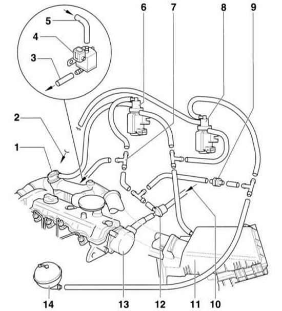
- 1 exhaust gas recirculation valve
- 2 to the vacuum supply air pressure control box. At the turbocharger.
- 3 to vacuum damper box
- 4 changeover valve for intake manifold damper
The damper of the inlet pipeline reduces jerks at a stop of the engine. The AGR engine is not always installed.
- 5 pipeline from the tee -7-
- 6 EGR adjustment valve
- 7 tee
- 8 supply air pressure limiting solenoid valve
- 9 check valve
- 10 from brake booster
- 11 air filter
- 12 check valve
- 13 vacuum pump
- 14 vacuum tank
Warning: The illustration shows ALH and AHF engines. AGR engines do not have a vacuum air pressure control system. Explanations for the operation of the exhaust gas recirculation system are given in subsection Operation of the catalytic converter.
High pressure fuel pump
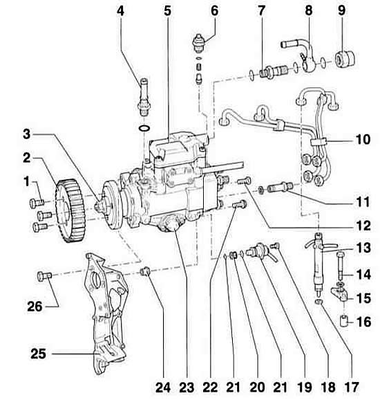
- 1 bolt, tightening torque: 20 Nm + 1/4 turn (90°). Be sure to replace.
- 2 gear wheel injection pump
- 3 nut. Turning off is not allowed.
- 4 connecting fitting, 25 Nm. For supply line, from fuel filter.
- 5 injection pump
- 6 fuel cut off valve, 40 Nm
- 7 connecting fitting. For return line.
- 8 return pipeline. To the fuel filter.
- 9 nut, 25 Nm
- 10 high pressure pipes, 25 Nm
- 11 connecting nipple, 45 Nm
- 12 bolt, 25 Nm
- 13 nozzle. The nozzle of the third cylinder has a needle displacement sensor.
- 14 bolt, 20 Nm
- 15 collar
- 16 support
- 17 heat seal. Be sure to replace.
- 18 bolt, 10 Nm
- 19 fuel injection start valve
- 20 mesh
- 21 O-ring. Be sure to replace.
- 22 bolt, 25 Nm
- 23 injection regulator cover
- 24 sleeve with nut
- 25 console
- 26 bolt, 25 Nm
Here, the injection pump directly injects fuel into the combustion chamber, namely, into the cavity in the piston. At the same time, the injection pump creates a pressure of 900 bar and injects fuel in two stages.
Thanks to the multi-nozzle nozzles and the double-spring nozzle holder, a small amount of fuel is first injected, which, when burned, creates favorable conditions for the injection of the main amount of fuel. This injection process provides soft and silent combustion similar to swirl chamber combustion. The amount of injected fuel is controlled by an electronic control unit. The advantage of this injection is to reduce fuel consumption by almost 20%. Signals from various sensors are used as control parameters for the injection process. These include:
- Pedal sensor that informs the control device about the position of the gas pedal. There is no gas supply to the injection pump.
- RPM sensor.
- Needle movement sensor at the nozzle. Thanks to this sensor, the start of injection is determined and the injection process is controlled depending on the load and engine speed.
- Supply air pressure sensor.
- Supply air temperature sensor.
- Coolant temperature sensor.
- Fuel temperature sensor.
- Adjusting damper travel potentiometer. The signals are used by the control unit as feedback to accurately position the control flap in the injection pump, which is an indication of the actual amount of fuel injected.
To achieve a high quality of fuel combustion, the suction channel is designed in such a way that the air on its way to the combustion chamber receives a vortex trajectory. Due to the better cold starting properties of a direct injection engine, preglow is only required at temperatures below -10°C.
Before entering the injection pump, the fuel passes through the fuel filter. The filter separates the fuel from water and contaminants. Therefore, it is important to remove water from the fuel and replace the filter element in a timely manner in accordance with the maintenance plan.
The injection pump does not require maintenance. Pump parts are lubricated with diesel fuel. The pump is driven by the crankshaft through a toothed belt.
Warning: When working on the diesel fuel system, safety and cleanliness must be observed.
Visitor comments