Repair Chevrolet Repair Toyota Repair Honda Repair AvtoVAZ Repair Mercedes-Benz Repair BMW Repair Opel
Home  |  Contacts  |  Sitemap  |    
English Русский
Български
Беларускі
Український
Српски
Hrvatski
Română
Polski
Slovenský
Magyar
AudiManual.ru


  • AUDI 80
  • AUDI 100
  • AUDI A3
  • AUDI A4
  • AUDI A6
  • AUDI A8
  • AUDI Q
  • OTHER
  • ARTICLES
C5 Allroad (1999-2005) C5 (1997-2004) C4 (1994-1997)

Electrical diagram of the control unit of the direct injection device of diesel, relay of the direct injection device of diesel, fuse other (Audi A6 C5)

  • Home
  • Audi A6
  • C5 (1997-2004)
  • Electrical equipment
  • Electrical circuits
  • Electrical diagram of the control unit of the direct injection device of diesel, relay of the direct injection device of diesel, fuse other
            0
Scheme 36. Control unit of direct diesel injection device, relay of direct diesel injection device, fuse, valves of cars with AFN/AVG diesel engines

Scheme 36. Control unit of direct diesel injection device, relay of direct diesel injection device,…
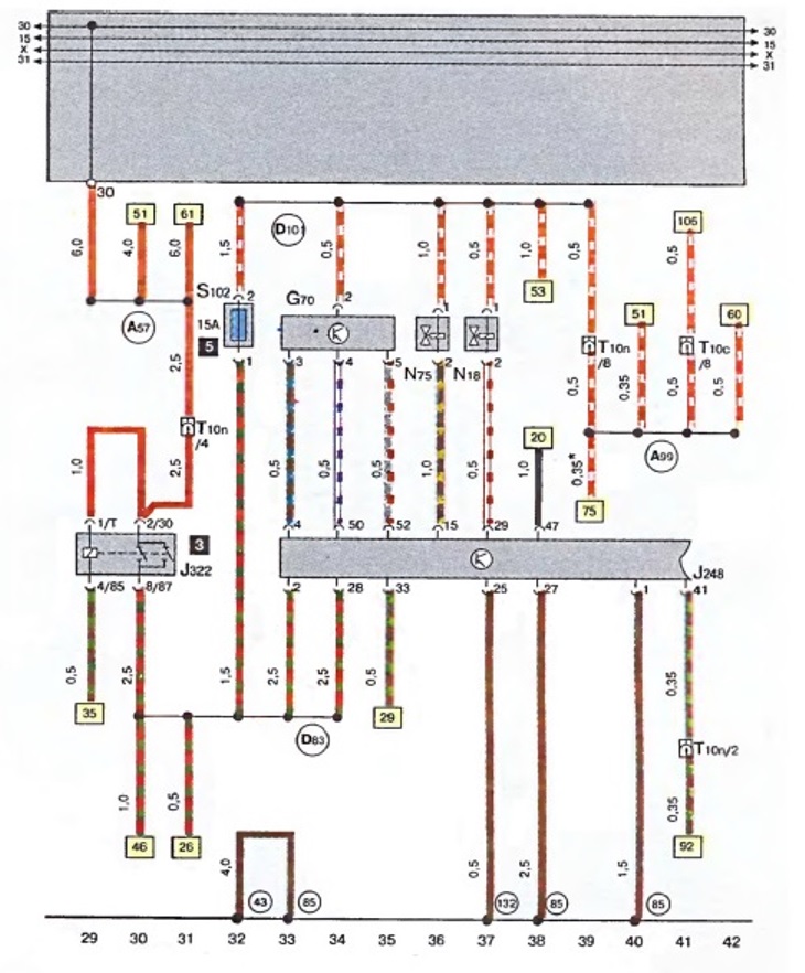
  • G 70 - air mass flow meter
  • J 248 - control unit for direct diesel injection device
  • J 322 - Diesel direct injection device relay
  • N18 - Exhaust gas bleed valve
  • N 75 - boost pressure limiting electromagnetic valve
  • S 102 - Engine control unit fuse
  • T 10 c - plug connection, 10-pin, grey, connecting clamp for post A, left
  • T 10 n - plug connection, 10-pin, orange color, connecting clamp for water tank E-Box
  • 43 - point of "mass", pillar A - on the right, below
  • 85 - connection to the body ("ground") "1", in the wiring harness of the engine compartment
  • 132 - connection to the body ("ground") "3", in the wiring harness of the engine compartment
  • A 57 - connection (30c), in the instrument cluster wiring harness
  • A 99 - connection "1" (87), in the instrument cluster wiring harness
  • 83 - connection (87), in the engine compartment wiring harness
  • D 101 - connection "1", in the engine compartment wiring harness

* - vehicles with speed control device

[Text provided by the online resource: AudiManual.ru]
The article was checked by auto expert Alexey Ivanov
This article is available at russian, bulgarian, belarusian, ukrainian, serbian, croatian, romanian, polish, slovak, hungarian

Share information:
Previous articles
Audi A6 C5: Electrical circuits
Next articles

Electrical diagram of glow plugs, relay for glow plugs, reverse…
Electrical diagram of the battery, starter, three-phase…
Wiring diagram for instrument cluster display, trip meter fuse…
Electrical diagram of the reverse light, engine cooling system
Electrical diagram of the control unit of the direct diesel…
Electrical diagram of the control unit of the direct injection…
Electrical diagram of the control unit of the direct diesel…
Wiring diagram of the instrument cluster display, control lamps,…


Similar articles on other Audi car models:
Electrical diagram of the fuel pump, fuel injection system,… Audi 80 B4 (1991-1996)
Mono-Motronic injection system control unit, fuel pump relay,… Audi 100 C4 (1990-1994, petrol)
Direct injection device (diesel) Audi A3 Type 8L (1996-2003)
Scheme 4. Direct fuel injection system of diesel engines Audi A4 B5 (1994-2001)
Draining water from the fuel filter of a V6 TDI diesel engine Audi A8 D2 (1994-2002)
Comfort system control unit, heated rear window and its relay,… Audi Q7 Typ 4L (2005-2015, diesel)
Electrical diagram of the 1.4 liter diesel engine AMF Audi A2 (1999-2005)
Link to this page in different formats


Visitor comments

No comments yet


How much will 20 + 34 =


A6(C5 AR, 1999-2005) 
  • General information
  • User manual
  • Maintenance
  • Troubleshooting
  • Power unit
  • V6 petrol engines
  • V8 petrol engines
  • Diesel engines
  • Cooling and heating system
  • Injection system (gasoline)
  • Fuel system (diesel)
  • Supply system
  • Exhaust system
  • Ignition system
  • Transmission
  • Clutch
  • Mechanical gearbox
  • Automatic gearbox
  • Chassis
  • Brake system
  • Car suspension
  • Steering
  • Body
  • Body elements
  • Doors, locks and windows
  • Electrical equipment
  • Equipment and devices
  • Power devices
  • Electrical circuits
  • Schemes (petrol engine 2.7 l)
  • Schemes (petrol engine 4.2 l)
  • Schemes (diesel engine 2.5 l)
 
A6(C5, 1997-2004) 
  • General information
  • User manual
  • Maintenance
  • Power unit
  • Engine repair
  • Cooling system
  • Fuel system
  • Engine management
  • Fuel system (diesel)
  • Exhaust system
  • Transmission
  • Clutch
  • Car gearbox
  • Chassis
  • Front suspension
  • Rear suspension
  • Steering
  • Wheels and tires
  • Brake system
  • Body
  • Exterior
  • Interior
  • Electrical equipment
  • Air conditioner
  • Equipment and devices
  • Electrical circuits
 
A6(C4, 1994-1997) 
  • General information
  • User manual
  • Maintenance (gasoline)
  • Maintenance (Diesel)
  • Gasoline engines
  • 4 cylinder engines
  • 5 cylinder engines
  • 6 cylinder engines
  • Diesel engines
  • 4 cylinder engines
  • 5 cylinder engines
  • Engine repair
  • Removal and reassembly
  • Cooling system
  • Single point injection system
  • Multipoint injection system
  • MPI/MPFI injection system
  • Fuel system (diesel)
  • Exhaust system
  • Ignition system
  • Transmission
  • Clutch
  • Manual transmission
  • Automatic transmission
  • Drive shafts
  • Chassis
  • Brake system
  • Front suspension
  • Rear suspension
  • Steering
  • Body
  • Exterior (external elements)
  • Interior (internal elements)
  • Electrical equipment
  • Power devices
  • Lighting and appliances
  • Electrical circuits
 
AudiManual.ru © 2017-2026 · Mobile version · Feedback · Sitemap: EN BG BY UA RS HR RO PL SK HU · Site search · News and articles
80 B2 · 80 B3 petrol · 80 B3 · 80 B4 · 100 C3 diesel · 100 C3 petrol · 100 C3 · 100 C4 petrol · 100 C4 · A3 Type 8L · A4 B5 petrol · A4 B5 · A4 B6 petrol · A4 B6 · A4 B7 · A4 B8 · A6 C4 · A6 C5 · A6 C5 Allroad · A8 D2 · Q5 Type 8R · Q7 Typ 4L · Audi A2 ·
This site uses cookies 🍪. Click the button to accept this fact.