
Table of contents: Technical specifications ↓ Overview of installation locations ↓ Accelerator Pedal Position Sensor… ↓ Clutch pedal position sensor "G476"… ↓ Pump of forced circulation of… ↓ Oil pressure regulating valve "N428"… ↓ Fuel pressure sensor "G247" "1" ↓ Intake manifold flap valve "N316" "2" ↓ Intake manifold flap potentiometer… ↓ Hall sensor "G40" "1" ↓ Electrical plug connections ↓ Coolant temperature sensor "G62" "1" ↓ Boost pressure sensor "G31" "1" ↓ Air filter parts and components ↓ Remove the air filter housing ↓ Remove the vacuum line "arrow" (if… ↓ Install ↓ Fuel rail ↓ Removal the intake manifold ↓ Install ↓ Removal ↓ Install ↓ Tightening torque ↓ Removal injectors ↓ Replacement of engine control unit… ↓ Install ↓
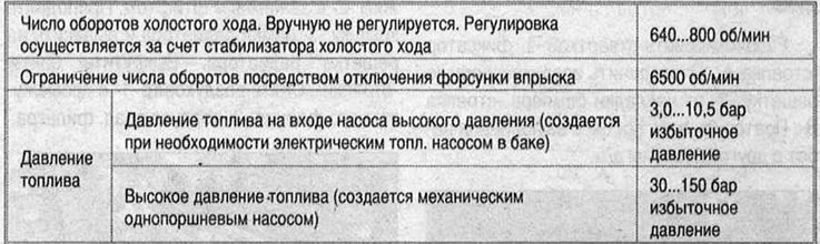
Technical specifications
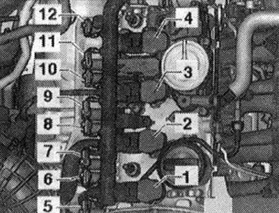
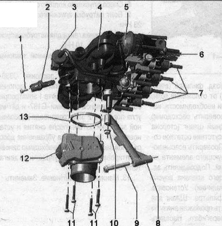
Overview of installation locations
Components A through I are not shown in the exploded view drawing.
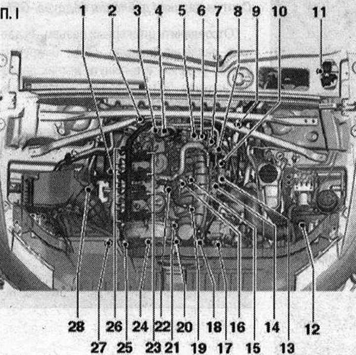
I 1. Lambda probe "G39" and heating element of lambda probe "Z19"; 2. Lambda probe after catalytic converter "G130" and heating element of lambda probe 1 after catalytic converter "Z29"; 3. Fuel pressure regulator "N₂76"; 4. High pressure fuel pump; 5. Vacuum reservoir for charge air regulating flaps (intake manifold regulating flaps); 6. Intake manifold flap valve "N316"; 7. Engine speed sensor "G28". 4.5 Nm; 8. Electromagnetic valve 1 of the absorber with activated carbon "N80"; 9.6-pin plug connectors for lambda probe "G39" and lambda probe heating element "Z19" (black). Lambda probe after catalytic converter "G130" and lambda probe 1 heating after catalytic converter "Z29" (brown plug); 10. Plug connectors. For knock sensor 1 "G61", intake manifold flap valve "N316", fuel pressure sensor "G247", intake manifold flap potentiometer "G336", coolant temperature sensor "G62", Hall sensor "G40" and injectors N30...N33; 11. Used engine "J623"; 12. Boost pressure sensor "G31"; 13. Throttle control unit "J338", throttle actuator (electronic throttle control) "G186". Throttle valve drive angle sensor "G187" and throttle valve drive angle sensor 2 "G188". After each removal and installation, or after replacing the throttle valve control unit "J338", it must be re-adapted to the engine control unit "J623"; 14. Intake air temperature sensor "G42"; 15. Knock sensor I "G61". To remove, it is necessary to dismantle the coolant pump with thermostat. Tightening torque: 20 Nm; 16. Coolant temperature sensor "G62"; 17. Fuel pressure sensor "G247"; 18. Oil pressure regulating valve "N428"; 19. Oil pressure sensor for low pressure "F378"; 20. Oil pressure sensor "F22"; 21. Intake manifold flap potentiometer "G336"; 22. Hall sensor "G40"; 23. Ignition coils with final stages. Ignition coils should be removed from the cylinder head using the puller "T40039"; 24. Valve 1 for adjusting the timing phases "N₂05"; 25. Turbocharger bypass valve "N₂49". Mounted directly on the turbocharger; 26. Actuating elements of camshaft phase regulation. Actuating element 1 of camshaft phase regulation "F366"; Actuator element 2 for adjusting the timing phases "F367"; Actuator element 3 for adjusting the timing phases "F368"; Actuator element 4 for adjusting the timing phases "F369"; Executive element 5 of the timing phase regulation "F370"; Executive element 6 of the timing phase regulation "F371"; Executive element 7 of the timing phase regulation "F372"; Actuator element 8 of the timing phase regulation "F373"; 27. Electromagnetic boost pressure limiting valve "N75". Installed directly on the turbocharger; 28. Air flow meter "G70"
A. Brake light switch "F" and brake pedal sensor "F47". In the footwell on the brake pedal
B. Clutch pedal position sensor "G476" (installed only on vehicles with manual transmission)
C. Accelerator pedal position sensor "G79" and accelerator pedal position sensor 2 "G185". On the accelerator pedal (both sensors are placed in 1 housing)
D. Used fuel pump "J538"
F. Used radiator fan "J293". Built into the radiator fan
G. Injectors. Injector cylinder 1 "N30"; Injector cylinder 2 "N31"; Injector cylinder 3 "N32"; Injector cylinder 4 "N33"
H. Pump for forced circulation of coolant "V51". Installed only on cars for countries with hot climates
I. Left electromagnetic valve of electrohydraulic engine support "N144" (not installed on all vehicles(depending on the CP)
Used engine "J623". In the left switching unit of the engine compartment
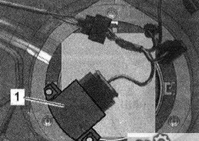
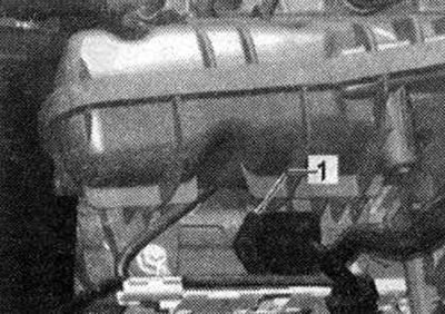
Used fuel pump "J538" "1"
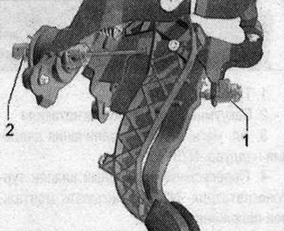
Accelerator Pedal Position Sensor "G79" and Accelerator Pedal Position Sensor 2 "G185"
2. Plug connector
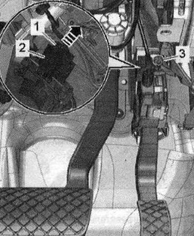
Clutch pedal position sensor "G476" "2"
Built-in components: Clutch pedal switch for engine start "F194" and clutch pedal switch "F36" (only for manual transmission)
1. Brake light switch "F" and brake pedal sensor "F47"
Pump of forced circulation of coolant "V51"
1. Electrical plug connector for coolant recovery pump "V51"
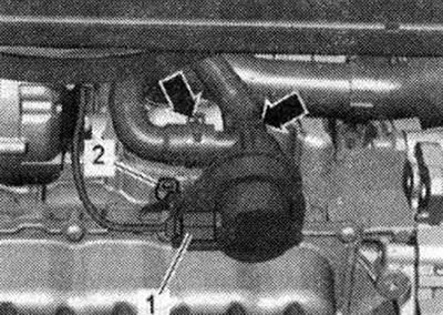
Installed only on vehicles for countries with hot climates.
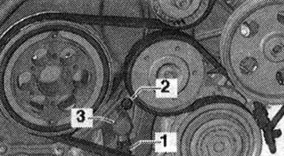
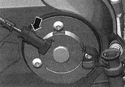
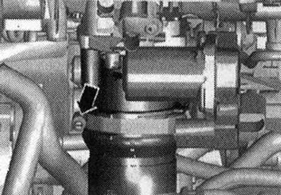
Oil pressure regulating valve "N428" "3"
Ignition coil 1. Ignition coil 1 with output stage "N702"; 2. Ignition coil 2 with output stage "N1273"; 3. Ignition coil 3 with output stage "N₂914"; 4. Ignition coil 4 with output stage "N₂925"; 5. Executive element 2 of the timing phase regulation "P367" (cylinder 1); 6. Executive element 1 of the timing phase regulation "P366" (cylinder 1); 7. Executive element 3 of the timing phase regulation "G368" (cylinder 2); 8. Executive element 4 of the timing phase regulation "P369" (cylinder 2); 9. Executive element 6 of the timing phase regulation "F371" (cylinder 3); 10. Executive element 5 of the timing phase regulation "P370" (cylinder indra 3); 11. Executive element 7 of the timing phase regulation "P372" (cylinder 4); 12. Executive element 8 of the timing phase regulation "P373" (cylinder indra 4)
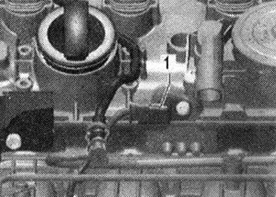
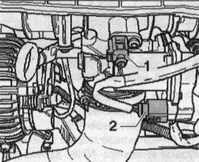
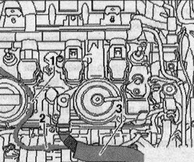
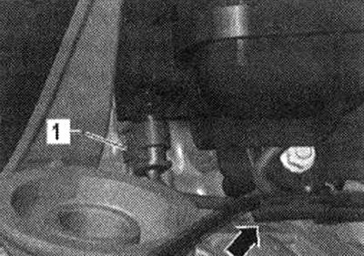
Fuel pressure sensor "G247" "1"
The tightening torque of the pipes 25 Nm must be checked before installing the fuel pressure sensor "G247"
Intake manifold flap valve "N316" "2"
1. Vacuum reservoir for intake manifold flaps
Intake manifold flap potentiometer "G336" "1"
Hall sensor "G40" "1"
Electrical plug connections
Electrical plug connections 1. From the electromagnetic valve 1 of the absorber with activated carbon "N80"; 2. Knock sensor 1 "G61"; 3. (14-pin) intake manifold flap valve "N316", fuel pressure sensor "G247", intake manifold flap potentiometer "G336", coolant temperature sensor "G62" and Hall sensor "G40"; 4. (8-pin) injectors N30...N33; 5. From the throttle body "J338"; 6. From the intake air temperature sensor "G42"
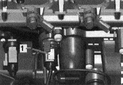
High pressure pump 1. Fuel pressure regulator "N₂762"; 2. High pressure pump. Fastening bolts "arrows"
Engine speed sensor "G28" -2
Valve 1 phase control FPM "N₂05" - arrow-
Details 1. Exhaust air temperature sensor "G42"; 2. Used throttle valve "J388"
Coolant temperature sensor "G62" "1"
Installation location under the intake manifold in the coolant pump
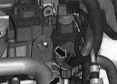
Boost pressure sensor "G31" "1"
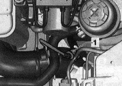
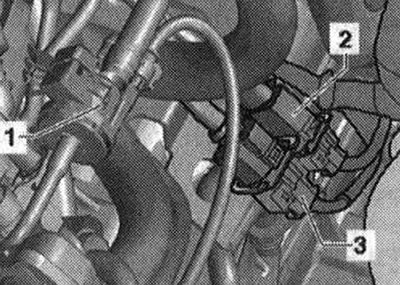
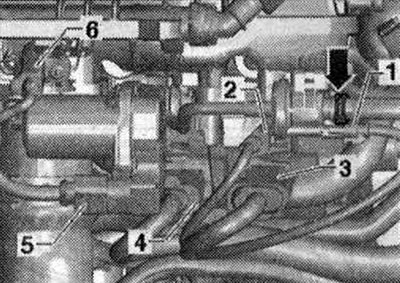
Node and electrical plug connectors 1. Electromagnetic valve 1 of the absorber with activated carbon "N80"; 2. Lambda probe after catalytic converter "G130" and heating element of lambda probe 1 after catalytic converter "Z29"; 3. Lambda probe "G39" and heating element of lambda probe "Z19"
Lambda probes 1. Lambda probe after catalytic converter "G130" and heating element of lambda probe 1 after catalytic converter "Z29"; 2. Lambda probe "G39" and heating element of lambda probe "Z19"
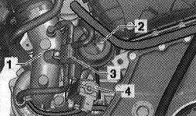
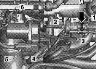
Components on a turbocharger 1. Turbocharger; 2. Turbocharger vacuum block; 3. Electromagnetic boost pressure limiting valve "N75"; 4. Turbocharger air bypass valve "N₂49" (take into account the installation position)
Air filter parts and components
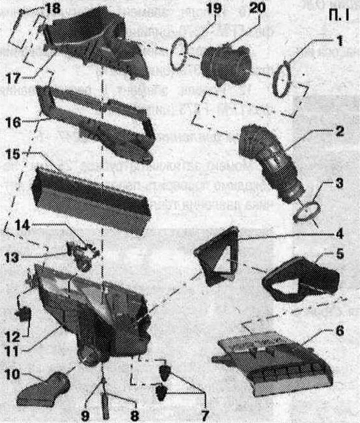
I 1. Hose clamp; 2. Air duct hose; 3. Hose clamp; 4. Air duct. Secured in the air filter housing. Clean the air duct from dirt and leaves; 5. Air duct. Clean the air duct from dirt and leaves; 6. Air duct. Tighten to the lock frame with a torque of 2 N·m. Clean the air duct from dirt and leaves; 7. Rubber bushing; 8. Water drain hose. Clean the water drain hose from dirt and leaves (important); 9. Water drainage hose guide; 10. Heated air supply line (only in countries with cold climates). Insert the heated air supply line into the air filter until it stops and turn it clockwise until it clicks; 11. Lower part of the air filter. Clean the lower part of the air filter from salt deposits, dirt and leaves. Note: check the drain for dirt, clean if necessary; 12. Fastening for the lower part of the air filter. Fix (with a clear feeling). Do not use lubricants; 13. Intake air changeover valve "N335". Parts (bypass flap with air intake changeover valve "N335"): not installed in all kit variants and not for all countries; 14. Bolt (only if air inlet changeover valve "N335" is installed); 15. Replacement air filter element. Always use the original filter element. Clean the fine filter as well (if installed); 16. Nozzle for the lower part of the air filter; 17. Upper part of the air filter. Clean the upper part of the air filter from salt deposits, dirt and leaves; 18. Bolt; 19. Sealing ring. Replace if damaged; 20. Air flow meter. Air flow meter "G70" with intake air temperature sensor "G42"
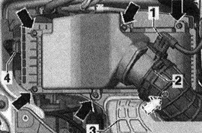
Remove the air filter housing
Disconnect the electrical plug connection "1" from the air mass meter "G70". Open the clamp "2" of the air duct leading to the turbocharger and remove the hose from the air mass meter "G70". Remove the air duct "3".
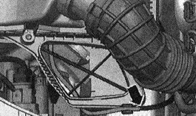
Remove the vacuum line "arrow" (if available).
Unlock the fastening "4" of the lower part of the air filter (press the rubber parts on the right and left and remove upwards). Parts (bypass valve with air inlet changeover valve "N335" "1") are not installed in all kit variants and not for all countries. When installing the fastener, do not use lubricants. Disconnect the electrical connector of the air inlet switching valve "N335" (if available). Carefully remove the air filter housing.
Install
For the G70 air flow meter to function properly, it is essential to perform the following steps. If the replaceable air filter element is heavily soiled or saturated with moisture, dirt particles or moisture may enter the G70 air flow meter and distort the data obtained. This causes a lack of power associated with a decrease in the calculated amount of fuel injected. Use only the original filter element. Use sealant to install the air intake sleeve (silicone free). To secure all hose connections, use clamps of the appropriate series. If a warm air suction pipe is installed (only in the version for countries with cold climates), ensure that the suction pipe "arrow" is correctly fixed (follow the markings). Check the condensate drain hose "1" at the bottom of the air filter for dirt and clots (clean if necessary).
Clean the air filter housing (upper and lower part) from salt, dirt or leaf deposits (if necessary, using a vacuum cleaner). Check the air flow meter and air duct hose (side of clean air) for salt, dirt and leaves. Check the suction channel up to the filter element for contamination. Connect the electrical connector of the air inlet changeover valve -N335 (if available). Install the lower part of the air filter. The water drain hose should be laid straight at the bottom and should not be kinked. Attach the vacuum hose "3" (if available) on the air inlet switching valve branch pipe "N335" "1". Carefully, without applying much force, install the upper part of the air filter onto the lower one.
Before tightening the bolts, check again that the upper part is located in the groove of the lower part of the air filter (air leakage through leaks). Screw the upper part of the air filter to the lower part. Check the tightness of the air supply hose on the air flow meter "G70". Reconnect the plug connector of the air flow meter "G70". Installation in the reverse order.
Intake manifold 1. Bolt of intake air temperature sensor "G42". 9 Nm; 2. Intake air temperature sensor "G42". Electromagnetic valve 1 of activated carbon absorber "N80"; 4. Intake manifold 10 Nm; 5. Vacuum reservoir for charge air regulating flaps (intake manifold regulating flaps); 6. Intake manifold flap valve "N316"; 7. Injectors. Replace the seal and Teflon rings. Consider the installation position; 8. Intake manifold support; 9. Intake manifold pipe bolt. 23 Nm; 10. Fastening nut for intake manifold pipe. 10 Nm; 11. Throttle body bolts "J338". 9 Nm; 12. Used throttle valve "J338", throttle actuator "G186". Throttle actuator angle sensor 1 "G187" and throttle actuator angle sensor 2 "G188". After removing and installing, or replacing the throttle actuator control unit "J338", it is necessary to re-adapt it to the engine control unit "J623"; 13. Lip seal. Replace
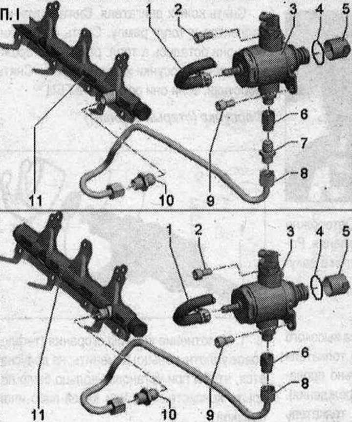
Fuel rail
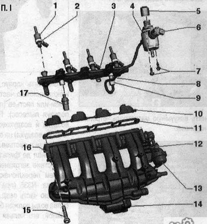
I 1. Injector. Always replace together with combustion chamber seal (teflon sealing ring). Replace the sealing rings. Observe the installation position; 2. Support ring; 3. Fuel rail; 4. High-pressure fuel pump with fuel pressure regulating valve "N₂76". In the fuel tank there is an electric fuel pump, which supplies fuel to the mechanical high-pressure pump. When installing the high-pressure pump, it is necessary to ensure that dirt does not get into the fuel system. Before installing the high-pressure pump, the fuel system must not be under pressure, relieve the pressure. Install the fuel lines without distortions; 5. Roller pusher; 6. Fuel pressure regulator "N₂76"; 7. High pressure pump bolts. Tighten crosswise to 5 Nm and then tighten to 20 Nm; 8. Fuel supply line nipple to the fuel rail. Replace. 40 N·m; 9. Union nut of fuel supply line. 20 Nm; 10. Compression valves (intake manifold flaps); 11. Gasket. Replace; 12. Intake manifold; 13. Vacuum reservoir for charge air regulating flaps (intake manifold regulating flaps); 14. Used throttle valve "J338", electric throttle drive "G186". Angle sensor 1 of the electric throttle drive "G187" and angle sensor 2 of the electric throttle drive; throttle valve "G188". After each removal and installation, or after replacing the throttle valve control unit "J338", it must be re-adapted to the engine control unit "J623". 7 Nm; 15. Bolts for intake manifold. 10 Nm; 16. Intake manifold flap potentiometer "G336". After each removal and installation or replacement of the intake manifold flap potentiometer "G336" or the intake manifold, it is necessary to adapt the intake manifold flap potentiometer "G336" to the engine control unit "J623"; 17. Fuel pressure sensor "G247". 27 Nm. Lubricate the threads with clean oil
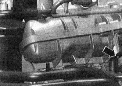
Removal the intake manifold
When removing or replacing the fuel rail, it is necessary to re-adapt the potentiometer of the intake manifold valve "G336" to the engine control unit "J623". To gain access to the injectors, it is necessary to remove the intake manifold with the fuel rail. Replace the combustion chamber seal (Teflon) and the sealing ring. Disconnect the negative terminal from the battery. Remove the engine casing. Disconnect the vacuum line "arrow" to the activated carbon canister. Disconnect the following electrical connectors.
1. Electromagnetic valve 1 of the absorber with activated carbon "N80"; 2. Knock sensor 1 "G61"; 3. From the intake manifold flap valve "N316", fuel pressure sensor G247 and Hall sensor "G40"; 4. From the injectors; 5. Used throttle valve "J338"; 6. Intake air temperature sensor "G42"
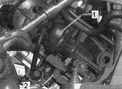
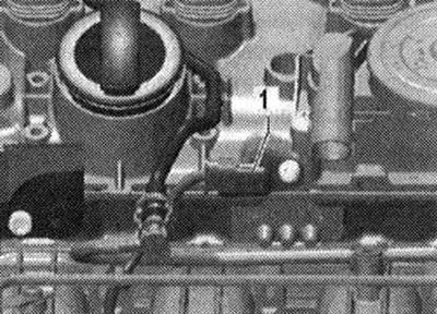
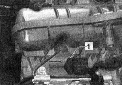
Disconnect connector "1" from Hall sensor "G40".
Open the clamp "arrow" of the air duct hose and disconnect the hose from the throttle module "J338" downwards.
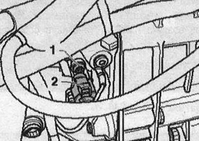
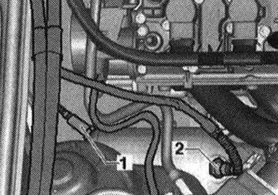
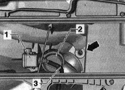
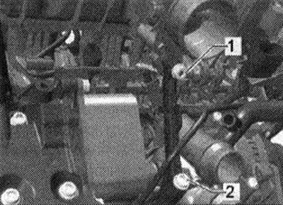
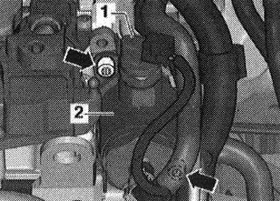
Disconnect the vacuum line "1" at the disconnection point "2". Disconnect the crankcase ventilation hose "3".
Open the spring clamp -upper arrow- and pull off the fuel supply hose from the high-pressure fuel pump. Open the union nut of the high-pressure fuel line "lower arrow" on the high-pressure fuel pump.
The fuel system must not be under pressure. Place a clean rag under the leaking fuel. Close the open fittings with clean plugs, make sure that no dirt gets into the fuel system. Remove the vacuum line "arrow" from the valve of the flap in the intake manifold "N316".
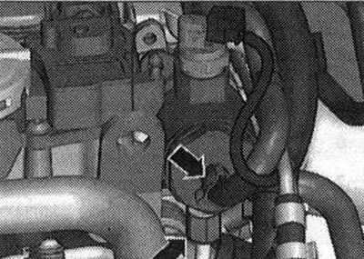
Unscrew the bolt "arrow" of the coolant line from the intake manifold.
Disconnect the electrical connector from the fuel pressure sensor "G247" "1".
Slightly loosen the fastening nut "1" and completely unscrew the bolt "2".
Disconnect the oil filter using the Hazet tension band "2171-1" or the oil filter key "3417" and remove the oil filter. Unscrew the bolts using the "T10347" key attachment from the intake manifold.
To unscrew inaccessible bolts without the "T10347" attachment, remove the throttle control module "J338". Carefully lift the intake manifold with the fuel rail from the cylinder head. Disconnect the connector "1" of the throttle potentiometer in the intake manifold "G336" and remove the intake manifold.
The injectors may remain in the fuel rail. Cover the intake ports with a clean rag. Separate the intake manifold from the fuel rail.
Install
Ensure that the injectors are installed correctly. Mount the intake manifold through the mounting pins (left and right below) on the cylinder head. Installation in reverse order.
Parts and units of high pressure pump
I 1. Fuel supply line from the fuel tank; 2. High pressure pump bolts. Tighten crosswise to 5 Nm and then tighten to 20 Nm; 3. High-pressure fuel pump. There is an electric fuel pump in the fuel tank that supplies fuel to the mechanical high-pressure pump. When installing the high-pressure pump, make sure that no dirt gets into the fuel system. Before installing the high-pressure pump, the fuel system must not be under pressure, relieve the pressure. Install the fuel lines without distortions; 4. Sealing ring. Replace; 5. Roller tappet. Sometimes remains in the vacuum pump after the high pressure pump is removed; 6. Connecting pipe. Not a spare part, an integral part of the high-pressure pump. Do not loosen; 7. Adapter. Depending on the design, an adapter is installed between the connecting nipple and the fuel supply line. If the adapter is installed, it should be replaced. 25 N·m; 8. High-pressure fuel line. Install the fuel line without distortions. 20 N·m; 9. High pressure pump bolts. Tighten crosswise to 5 Nm and then tighten to 20 Nm; 10. Fuel supply line nipple. Replace. Connecting pipe: 40 Nm. Tightening torque of the fuel supply line union nut: 20 Nm. Install the fuel supply line without distortions (keep clean)
Removal
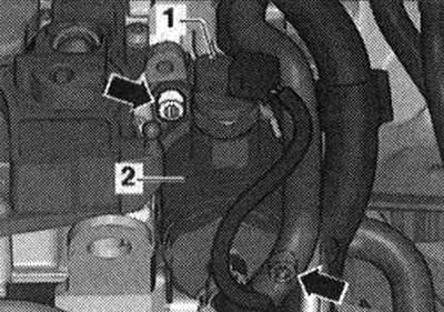
The high-pressure pump must only be installed and removed when the engine is cold. When installing the high-pressure pump, ensure that no dirt gets into the fuel system. Collect any leaking fuel with a rag. Always replace the sealing ring. Always secure the high-pressure fuel lines so that they are free of internal mechanical stress. Remove the engine casing. Disconnect electrical connector "1" from the fuel pressure regulating valve "N₂76".
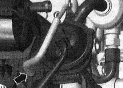
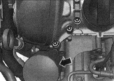
Disconnect both fuel lines "arrows".
Unscrew the 2 "arrow" screws. Carefully remove the high-pressure fuel pump. The roller tappet sometimes remains in the vacuum pump.
Install
Replace the high pressure pump sealing ring. Install the roller tappet into the vacuum pump (pre-check the roller follower for damage). To install the injection pump, the roller tappet must be in the lowest position. When installing the same or a used injection pump, it is necessary to replace the connecting nipple for the fuel supply line (high pressure side). Rotate the cardan shaft so that the roller tappet is in the lowest position. Install the fuel injection pump into the vacuum pump and secure it. Tighten the bolts by hand.
Tightening torque
Now tighten all bolts crosswise to the prescribed tightening torque, see high-pressure pump. Tighten the union nut of the fuel supply line by hand. Align without distortion and tension. Tightening torque of the fuel supply line (union nut): high pressure pump installation diagram. Reconnect connector "1" of fuel pressure regulating valve "N₂76". If the fuse was removed, reinstall it. Check fuel system for leaks.
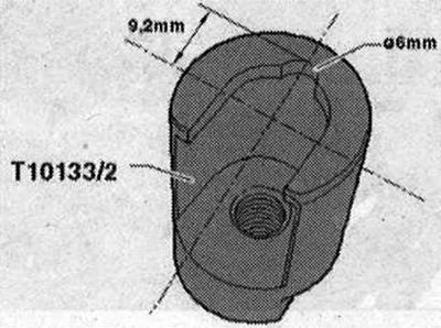
Removal injectors
Cut out a semicircle as shown in the picture. The semicircle allows the tool to be placed deeper on the nozzle, which provides a larger plane of contact for the tool. The letter "A" should be written at the end of the serial number of the converted tool.
Remove the engine cover. Remove the intake manifold and fuel rail. Remove the injectors if they are still in the fuel rail. Carefully remove the injectors from the fuel rail. Remove the injectors if they are still in the cylinder head
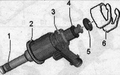
Nozzle (old version) 1. Combustion chamber seal (teflon sealing ring) replace; it is not permissible for the ring to be covered with grease or any other lubricant during installation.; 2. The support ring is replaced by an intermediate ring. See the following figure; 3. Nozzle; 4. Spacer ring (replace if damaged); 5. Sealing ring (replace, lightly lubricate with clean oil when installing); 6. Support ring (through this support ring the fuel rail transmits the force that holds the injector in the cylinder head)
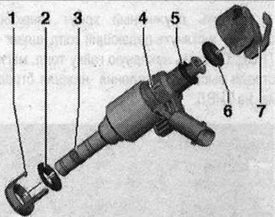
Nozzle (new version) 1. Replace the intermediate ring; 2. Emphasis; 3. Sealing the combustion chamber (teflon sealing ring) replace; it is not permissible for the ring to be covered with grease or any other lubricant during installation.; 4. Nozzle; 5. Spacer ring (replace if damaged); 6. Sealing ring (replace, lightly lubricate with clean oil when installing); 7. Support ring (through this support ring the fuel rail transmits the force that holds the injector in the cylinder head).
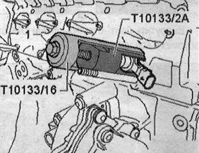
Cover the open intake ports with a clean cloth. Disconnect the plug connector from the injector to be removed. Insert the "T10133/2A" puller into the injector groove. Install the "T10133/16" puller and remove the injector by turning bolt "1".
The combustion chamber seal must be replaced before reinstalling the injector.
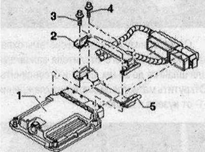
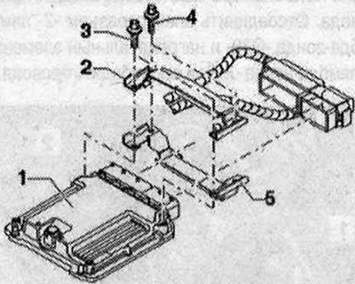
Replacement of engine control unit "J623"
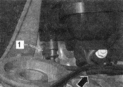
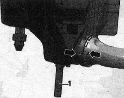
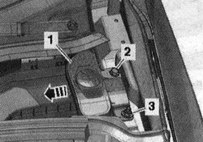
Not every engine control unit is screwed with a protective housing. The installation of the protective housing depends on the combination "engine - gearbox". Used engine "1" is screwed with a protective housing "2 and 5". To prevent the shear screws "4" of the retainer "2" from unscrewing, a fixing varnish is applied to their threads. So that it is possible to remove the plug connections from the engine control unit (for example, to connect a diagnostic unit or replace an engine control unit), it is necessary to dismantle the protective housing. If 1 protective housing is installed, then special tools are required. When replacing the engine control unit, select the "Guided functions" mode in the tester, the diagnostic object "Replace the engine control unit". Turn off the ignition and remove the key from the ignition switch. Unscrew the nut "3" and bolt "2". Remove the filler neck "1" with the filler tube from the washer reservoir, passing it through the body opening "arrow".
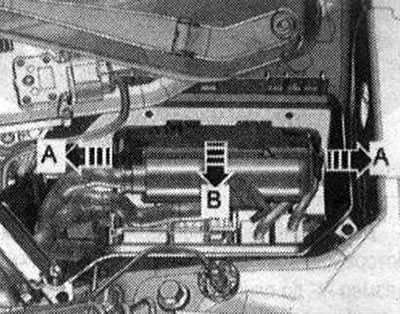
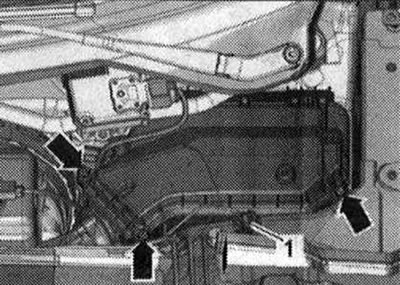
Unscrew the "Arrow" bolts and remove the cover of the switching unit.
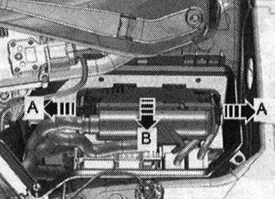
Unlock the clamps "arrow A" and remove the engine control unit "J623" "arrow B".
Further actions are necessary when installing the protective housing: To make it difficult to access the engine control unit connectors, the engine control unit "1" is connected with bolts through the lock "2" and locking bolts -3 "4" to the metal housing "5". On the threads of both locking bolts "4" (not bolted to used engine) thread varnish is applied. To unscrew both bolts, it is therefore necessary to heat their threads with an industrial hair dryer.
The threads of both locking bolts connected to the used engine "3" are not protected with thread varnish. Do not heat the threads in the control unit housing, this is not required (unacceptable heating of the engine control unit).
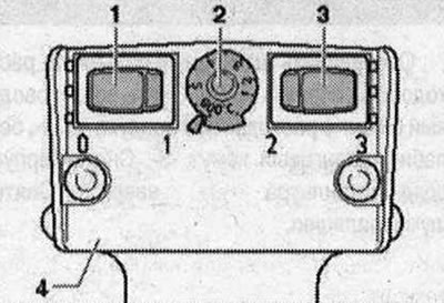
Adjust the heat gun as shown in the figure. This means that the temperature control potentiometer "2" should be set to maximum heating, and the two-stage blowing intensity switch "3" should be set to position 3. As a result of heating the thread of the retainer, the shear screws and parts of the protective housing become very hot. Do not burn yourself! Also, make sure that only the thread is heated, and not the adjacent parts, if possible. Cover them if necessary. Heat the thread of the shear bolts on the connector side as shown in the figure.
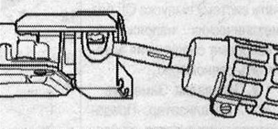
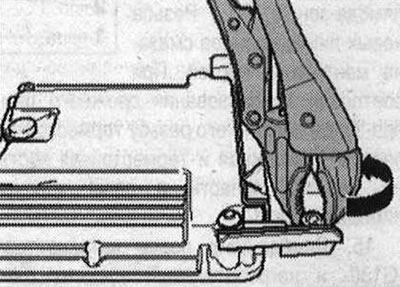
To do this, turn on the hair dryer and heat the bolt for about 20-30 seconds. Use pliers to unscrew the lock bolt (in the direction of the arrow).
Do not heat the two shear bolts screwed into the engine control unit. They should be unscrewed without heating. Disconnect the protective housing from the control unit connectors. Unlock the engine control unit connector and disconnect. Remove the old engine control unit "J623" and insert the new engine control unit "J623".
Install
Installation is carried out in reverse order. If a protective housing has been installed, the engine control unit "J623" must be fitted with a protective housing again. Clean the threaded holes of the shear bolts from any remaining thread varnish. A tap can be used for cleaning. Use only new shear bolts. The tightening torque of the switch box cover bolts is 3.5 Nm. After installing the new engine control unit, the following operation must be performed: activate the engine control unit in the "Guided functions" mode under "Replace engine control unit", for this purpose use a tester.