
Table of contents: Control unit ↓ Injection valves ↓ Fuel distribution pipe ↓ Fuel pressure regulator ↓ Fuel pump and relay ↓ Fresh air pressure meter ↓ Intake Manifold Air Pressure Sensor ↓ Fresh air flow temperature sensor ↓ Throttle body pipe ↓ Throttle potentiometer ↓ Idle speed control valve ↓
In order to better understand the functioning of the injection system as a whole, it is first important to learn about the tasks of its individual components.
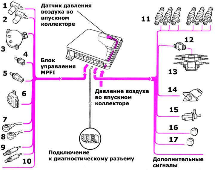
- 1 — Engine speed sensor
- 2 — Ignition timing sensor
- 3 - Hall sensor
- 4 — Coolant temperature sensor
- 5 — Intake air temperature sensor
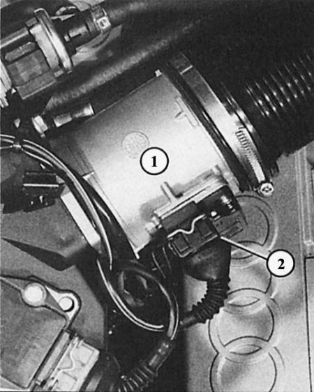
- 6 - Throttle potentiometer and idle speed switch
- 7 — Knock sensor I
- 8 — Knock Sensor II
- 9 — Lambda probe I
- 10 — Lambda probe II
- 11 — Injection valves
- 12 — Power output stage
- 13 - Dual ignition coils
- 14 — Idle speed control valve
- 15 — Carbon filter system electromagnetic valve
- 16 — Lambda probe heating control unit
- 17 — Fuel pump relay
This diagram illustrates the electrical side of the ignition/injection system, in this case using the MPFI example with the intake manifold air pressure sensor. On the left side are the sensors and gauges that influence the behavior of the control unit. On the right are the ignition and injection units to which the control unit sends its signals.
Fuel side of the MPI/MPFI ignition/injection system
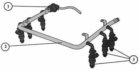
- 1 - fuel pressure regulator;
- 2 - fuel distribution pipe;
- 3 - injection valve.
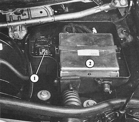
The control unit (2) for the MPI/MPFI ignition/injection system is located in the electronic box on the left rear of the engine compartment (in the so-called humidification tank). In the bracket next to the control unit here in the 2.6 l engine, the relay (1) for heating the lambda probes is located.
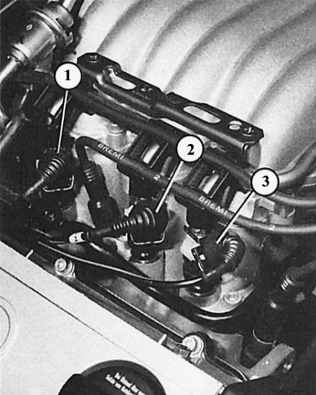
Left: The injection valves (1, 2 and 3) in the six-cylinder engine are located in groups of three to the right and left of the central intake manifold.
Right: At the rear right in the engine compartment is a fresh air flow meter (1), flanged to the air filter housing in a 2.8 liter engine. The number "2" indicates the connection socket.
Control unit
Between incoming information (from various sensors) and the injection valves are located in the electronic control unit. Depending on the existing load and temperature conditions, it sends a very specific amount of fuel to the engine. For this purpose, the control unit varies the duration of opening of the electromagnetically controlled injection valves. The amount of fuel injected can only be changed by the duration of injection. Information for determining the duration of injection comes to the control unit from various units, these are:
- Only in 2.8L MPI engine: Fresh air flow meter; it provides information about the amount of air being sucked in.
- Only in 2.6 engine with MPFI: intake air temperature sensor; in combination with the intake manifold air pressure sensor (in the control unit) it gives a comparative value of the amount/mass of air sucked in.
- Coolant temperature sensor; it provides a comparative value of engine temperature.
- Throttle potentiometer; it provides information about the engine load.
- Speed sensor; it transmits a signal about the crankshaft speed.
- The engine start signal comes from terminal 50 of the ignition switch (starter).
- Lambda probes send a signal about the correct composition of the fuel-air mixture.
- Other influencing values come from: knock sensors, gearbox, speedometer and, if present, the air conditioning system.
Injection valves
Each engine cylinder has one injection valve in the intake channel. It supplies each cylinder with the amount of fuel needed at the moment and at the same time ensures fine atomization of gasoline.
The valves are operated electromagnetically. This causes the metering needle to rise in its seat by approximately 0.1 mm – fuel can flow.
Fuel distribution pipe
It serves to supply fuel evenly to all injection valves. In addition, the distribution pipe functions as a manifold and thus prevents pressure fluctuations. The ring-shaped shape of the pipe is interesting, allowing fuel to be supplied to all six valves.
Fuel pressure regulator
It is located on the rear right side of the fuel rail and is designed to maintain a constant fuel pressure in the rail. It does this by increasing or decreasing the amount of fuel flowing through the recirculation pipe. If more fuel is returned, the pressure decreases; with a small return of fuel it rises.
By connecting the vacuum hose, the pressure regulator simultaneously receives information about the engine load status. At full load, it increases the pressure a little more. As a result, more fuel is injected, which the engine needs to achieve full power.
Fuel pump and relay
You will learn more about the electric fuel pump, fuel pump relay and other MPI/MPFI relays in the chapter Fuel tank and fuel pump.
Fresh air pressure meter
MPI only
A wire is placed in the intake air flow, which is heated electrically. Depending on the mass of the intake air, the air flow changes, which cools the wire more or less. The change in temperature causes a change in the resistance of the wire, and this is measured by the control unit.
Intake Manifold Air Pressure Sensor
MPFI only
The intake manifold air pressure sensor is located in the MPFI control unit. The intake manifold and the sensor are connected to each other by a thin hose. For the control unit, the intake manifold air pressure is the most important information for calculating the engine load. This affects the injection duration and the ignition timing.
Fresh air flow temperature sensor
MPFI only
The intake air temperature sensor is screwed into the intake channel of the third cylinder (back right). In addition to the air pressure sensor, it serves the control unit to calculate the engine load. At high intake air temperatures (equivalent to low air density) the injection time, for example, should be reduced and the ignition timing shifted slightly more in the "later" direction.
Throttle body pipe
Where the fresh air flow enters the engine's intake manifold, there are two throttle valves in the fitting. The smaller of these is connected by a throttle cable to a pedal in the cabin. It controls the flow of intake air into the engine to the half-throttle position.
As the pressure on the gas pedal increases, the linkage system opens the second, larger valve until, at full throttle, both throttle valves are fully open.
Throttle potentiometer
The throttle potentiometer is driven by the throttle shaft. The potentiometer detects the current position of the throttle valve and sends a signal to the control unit in the form of electrical voltage. This load information, among other signals, is used by the control unit to adjust idle speed, select ignition characteristics and calculate injection duration.
Idle speed control valve
As the name suggests, this valve ensures a constant idle speed – no matter whether the engine is warm or not, whether power consumers are connected (air conditioning system) or not.
The valve is only an actuator. The brain of the adjustment is the MPI or MPFI control unit. It compares the current speed with the nominal speed and ensures finely tuned opening and closing of the control valve, adjusting the speed. At the same time, the cross-section of the auxiliary air channel, which bypasses the throttle valve, changes. If the auxiliary channel is open, more air is sucked in, and therefore the fresh air flow meter "thinks" that the throttle valve is open. This, in turn, prompts the injection system to direct the required amount of fuel, which leads to an increase in engine speed.
It should also be noted that different idle speed stabilization valves are used: the continuously variable control valve MPI; valve driven by a so-called stepper motor in MPFI. The latter changes the bypass opening in small, precisely adjusted steps.
[The original article is available on the online resource AudiManual]