
Table of contents: Injection valves ↓ Throttle potentiometer ↓ Air mass meter ↓ Idle speed control valve ↓ Idle speed control valve ↓ Ignition/Injection System Coolant… ↓ Intake air temperature sensor ↓
The following sections describe tests of injection system components that can be performed using amateur tools.
Injection valves
If you suspect that one of the injection valves is not functioning, you can easily find out with the help of an LED voltage indicator and an accurate ohmmeter.
1. Remove the engine cover.
2. Disconnect the injection valve connectors.
3. Check the voltage first: connect the LED voltage indicator (not a control lamp) to the connector contacts. Start the engine: the LED in the voltage indicator should flash, if not, then there is no voltage or the control unit connecting the ground is faulty. This test cannot be performed with a measuring device.
4. Resistance test: disconnect the injection valve connectors, connect an ohmmeter to both valve contacts: if the engine is cold, the device will show 13.5–17 Ohms.
5. If the value is not tolerant, replace the valve (if the measurement was carried out accurately).
6. Checking for leaks: remove the fuel distribution pipe together with the injection valves.
7. The injection valve connectors are disconnected, the fuel lines remain connected.
8. Have your assistant turn the engine over with the starter several times to activate the fuel pump and build up fuel pressure.
9. Observe the injection valves: each of them should release a maximum of 1-2 drops of fuel per minute. Otherwise, replace the corresponding valve.
10. Regardless of this, you can check the injection stream and the amount of fuel injected by the valve if this is necessary due to engine malfunctions.
Throttle potentiometer
1. Disconnect the throttle potentiometer connector.
2. Using an accurate ohmmeter, measure the resistance between the potentiometer contacts.
|
Throttle position
|
Measuring between contacts
|
Nominal value (kOhm)
|
| Doesn't matter |
1 and 2
|
1,5–2,6
|
| Idling |
2 and 3
|
0,75–1,3
|
| Full throttle |
2 and 3
|
maximum 3.6
|
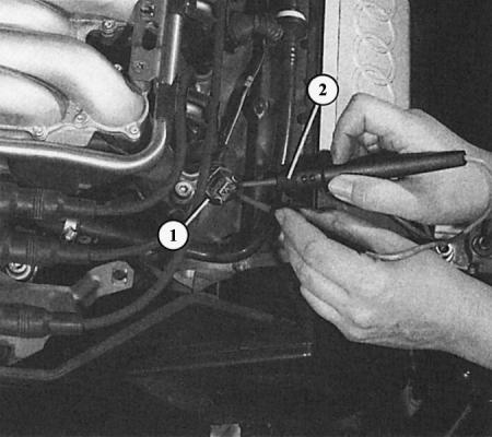
By disconnecting the connector (1), you can measure the voltage supply to the injection valves (2) using the LED voltage indicator. When the engine is turned over by the starter, the LEDs in the voltage indicator should flash. If not, then there is no voltage supply.
Air mass meter
MPI only
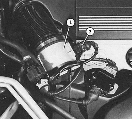
The photograph shows the air mass meter (1) of a 2.8L engine and the three-pin connector (2).
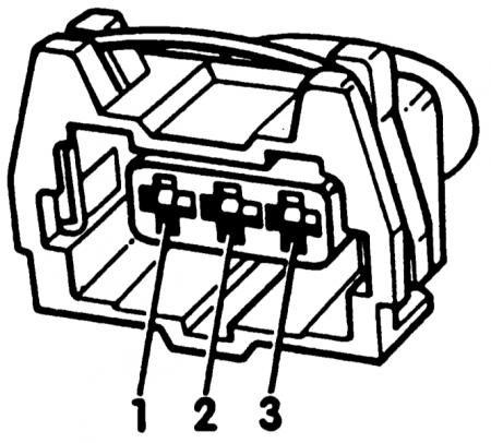
The three-pole connector pinout diagram is used to test the air mass meter.
1. Measurements are taken with the throttle valve in the "idle" and "full throttle" positions with the engine not running.
2. The following nominal values should be obtained:
3. Slide back the rubber cap on the air mass meter connector, the connector remains connected.
4. Connect an accurate voltmeter to the connector contacts at the rear as described below:
5. Measurement 1: Connect the test leads to terminals "2" and "3".
6. Turn on the ignition.
7. The voltmeter should show 12–14 V. If not, then there is a defect in the voltage supply.
8. Check fuse 32, if necessary, check the wire from fuse 32 to contact "3" of the air mass meter connector.
9. Or check the connection from engine ground to contact "2".
10. Measurement 2: Connect the test leads to terminals "1" and "2".
11. Turn on the ignition.
12. The voltmeter should show 0.3–1.1 V.
13. Start the engine (the wire remains connected). Turn off all consumers, the radiator fan should not work
14. Consistently fluctuate the engine speed between idle and 4000 rpm.
15. The voltmeter should show (depending on the number of revolutions) from 1.5 to maximum 3.4 V. If not, the air mass meter is faulty. Replace it.
Idle speed control valve
MPI only
In a 2.8L engine, the idle speed control valve is located on the right side of the throttle body.
1. Disconnect the idle air control valve connector and connect an accurate ohmmeter to both terminals of the valve connector.
2. The measuring device should show 7-11 Ohms, otherwise the valve is faulty.
3. A more in-depth check of functionality: remove the idle speed control valve; the connector remains connected.
4. Set the rotor in the air passage of the valve to the "open" or "closed" position (do not use a metal tool for this purpose).
5. Turn on the ignition and observe the rotor: it should oscillate approximately in the middle position.
6. Check the ease of movement of the rotor: it should move due to the jerky movement of the dismantled valve.
7. In addition, it should not have any nicks or abrasions.
Idle speed control valve
MPFI only
The photograph shows the idle speed control valve (arrow) in a 2.6L engine.
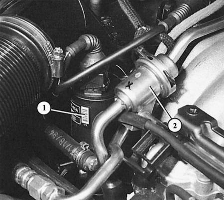
The idle air control valve (1) on the 2.8L six-cylinder engine is located next to the fuel pressure regulator (2), as you can see in this photo.
Attention! The idle speed stabilization valve of the 2.6 l engine cannot be removed in a home workshop, as immediately after installation a so-called basic adjustment of the injection system must be carried out, which can only be done using the VAG 1551 fault reading device in an Audi workshop.
If the connector on the idle air control valve is disconnected within 1/2 hour after the engine was last turned off, the "idle air control valve defect" fault will be stored in the computer's memory (which perhaps has not been done before).
In this valve only the winding is checked:
1. Disconnect the connector on the idle speed control valve.
2. Using an accurate ohmmeter, measure the resistance between connector contacts "1" and "4", as well as "2" and "3" of the valve.
3. If the valve is in working order, the device should show 45–60 Ohms, otherwise the valve should be considered defective.
4. It is not possible to carry out other checks on your own.
5. If the workshop replaces the valve, it immediately carries out the mentioned basic adjustment.
Ignition/Injection System Coolant Temperature Sensor
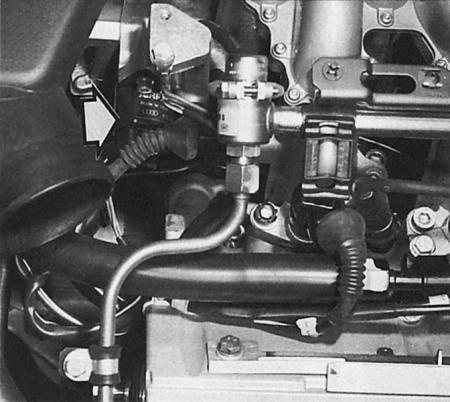
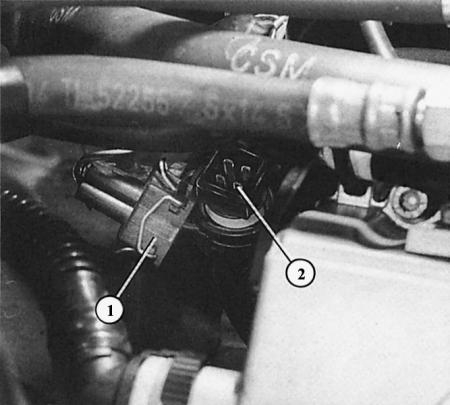
At the rear of the engine, screwed into the coolant supply pipe, is a combined coolant temperature sensor (1) for the ignition/injection system and a temperature indicator. Here, the connector (2) is disconnected to check the sensor. The connector contacts "1" and "3" are related to the injection system.
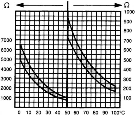
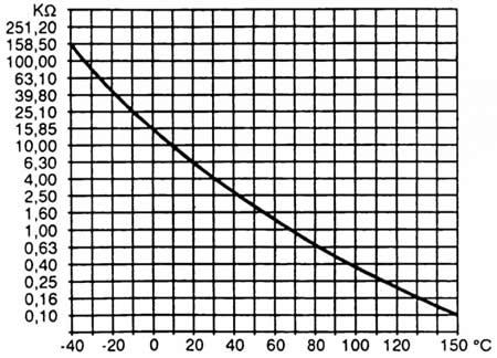
The diagram shows at what temperature what resistance value this sensor should show.
Caution! If the connector on the coolant temperature sensor in a 2.6L engine is disconnected within 1/2 hour after the last engine shutdown, the "coolant temperature sensor defect" fault will be stored in the computer's memory (which perhaps has not been done before).
General: The coolant temperature sensor may be the cause if engine performance issues occur in certain temperature ranges. Check:
1. Disconnect the connector on the coolant temperature sensor.
2. Use an ohmmeter to measure the resistance between connector contacts "1" and "3" of the sensor.
3. The measured resistance is compared depending on the engine temperature with the nominal value diagram below. If the value is significantly outside the curves, replace the temperature sensor.
4. In conclusion, two more approximate resistance values should be mentioned here: at a coolant temperature of 20°C, the ohmmeter should show about 2.5 kOhm, at 80°C – about 330 Ohm.
Intake air temperature sensor
MPFI only
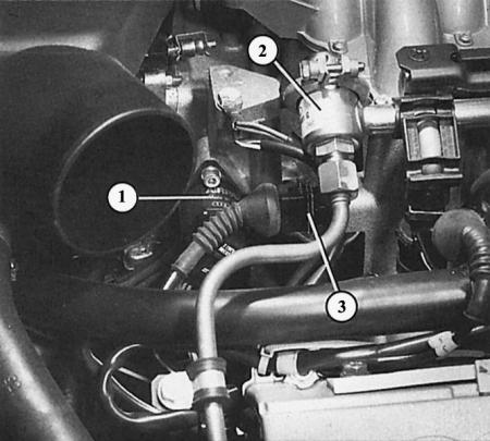
The intake air temperature sensor (3) is only present in the 2.6L engine. It is located on the right rear of the engine next to the idle speed control valve (1) and the fuel pressure regulator (2).
This diagram shows the resistance value of the sensor depending on the intake air temperature.
Caution! If the connector on the intake air temperature sensor is disconnected within 1.5 hours after the engine was last turned off, the fault "intake air temperature sensor defect" will be stored in the computer memory (which perhaps has not been done before).
1. Disconnect the intake air temperature sensor connector.
2. Measure the resistance between the two contacts of the sensor connector using an accurate ohmmeter.
3. Compare the measured resistance depending on the engine temperature with the nominal value in the diagram below. If the value is significantly outside the curves, replace the temperature sensor.
4. Finally, here is an approximate resistance value: at 20°C (room temperature, engine cold) the device should show about 6.3 kOhm.