
Table of contents: Checking the injectors ↓ Checking the cold start valve ↓ Checking the fuel dispenser ↓ Checking the air volume meter ↓ Position of the air measuring plate ↓ Checking the stabilization of idle… ↓ Checking the switch on the throttle… ↓ Adjusting the switch on the throttle… ↓ Checking the temperature sensor ↓
Below are described troubleshooting tasks that do not require special tools or devices.
Checking the injectors
Lock the ignition.
To check if fuel is reaching the injector, loosen the fuel line bolt on the cold start valve.
Keep a rag handy in case gasoline spills. If gasoline does not spill, have an assistant crank the starter.
If fuel is leaking, remove the injector.
Keep a vessel or rag ready.
Remove the large air hose between the mixture regulator and the throttle body to gain access to the air intake plate.
In the central assembly block, pull out the fuel pump relay and short-circuit contacts 3 and 87 on the block with a piece of wire. The fuel pump should start working.
Raise the air measuring plate in the distributor slightly by hand. The injector should emit a conical jet.
If this is not the case, lift the plate as far as it will go. Repeat the check.
Similarly, the difference in the amount of fuel injected for individual cylinders should be measured.
Each injector should be lowered into its measuring vessel so as not to damage the injectors.
Raise the air measuring plate slightly (by about 2 mm).
The assistant should keep the mentioned wire jumper inserted until 2 ml of fuel is poured into the first cup.
Compare the volumes of fuel in different cups. The deviation from each other should not exceed 3 cm³.
If the deviation is greater, swap the injectors with the highest and lowest output. Repeat the test.
If the performance has also changed, then the corresponding injectors need to be replaced.
If the result does not change upon rechecking, the line to the injector may be narrowed or the dispenser may be faulty.
Checking the tightness of the injectors: If you turn off the fuel pump after two minutes of operation with the air measuring plate raised, no fuel should leak through the injectors.
The installation of the injector is described below.
Checking the cold start valve
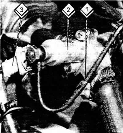
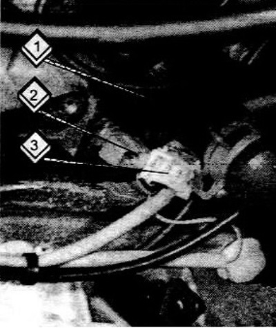
On the side of the intake pipe of the engine with a power of more than 10 kW, there is a cold start valve (2). The fuel supply line (1) and plug (3) are also visible here.
Lock the ignition.
Unscrew the cold start valve, disconnect the plug, leaving the fuel line connected. Briefly turn on the starter so that the fuel pump creates pressure.
Lower the valve into the vessel, connect two pieces of wire of sufficient length to the valve contacts.
Connect the free ends of the wires to the positive and negative terminals of the battery.
The valve should spray a cone-shaped stream of gasoline.
To check the density, you should disconnect the wires.
Turn the starter on again briefly to allow the fuel pump to build up pressure.
Wipe the valve dry. No gasoline should leak out within one minute.
Checking the fuel dispenser
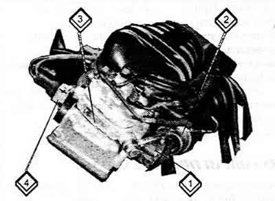
1 Diaphragm pressure regulator
2 Pressure regulator
3 Fuel dispenser
4 Throttle potentiometer
Not for long (about 1 second) start the engine or crank the starter to build up fuel pressure.
Loosen the clamps on the thick air hose between the mixture regulator and the throttle valve pipe, disconnect the hose.
Remove the air filter cover together with the mixture regulator screwed to it.
Raise the air measuring plate that appears completely upwards. The resistance of the plate should be the same all the way.
When you quickly push the plate back, there should be no resistance. If there is, the air flow meter needs to be replaced (flow meter).
If the plate goes up with difficulty and down easily, then the distribution piston is stuck in the dispenser. The fuel dispenser needs to be replaced.
Checking the air volume meter
Warm up the engine or let the warm engine run for approximately 1 second before performing the check.
Remove the air supply hose between the mixture regulator and the throttle valve pipe after loosening the clamping bands.
Position of the air measuring plate
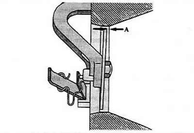
Check the air measuring plate. It should be in a certain position on the side facing the high-pressure fuel lines.
The plate should be 1.9-3 mm below the top edge.
If the position of the plate is incorrect, it can be lifted and its position adjusted by bending the retaining brackets. The flat spring must not be bent.
Check if the plate touches the wall.
If so, loosen the center mounting bolt and center the plate.
After this adjustment, the idle speed and CO content should be checked.
Checking the stabilization of idle speed
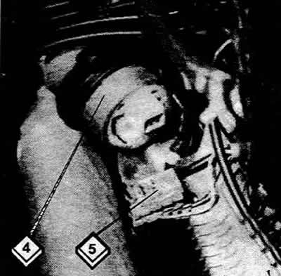
Idle speed stabilization valve (4) with disconnected plug (5)
Turn on the ignition. You should be able to feel the valve working.
Otherwise, the control valve or temperature sensor is faulty.
Checking the switch on the throttle shaft
Disconnect the plug to the switch on the throttle valve pipe. Connect an ohmmeter to the switch contacts and measure the resistance.
The resistance with the throttle valve closed should be zero, and with the throttle valve open it should be infinite.
To check the switch adjustment, slowly open and close the throttle valve.
When the distance from the throttle lever to the stop is 0.15 mm (measure with a flat feeler gauge), the switch should click clearly, in which case the adjustment will be correct.
Adjusting the switch on the throttle shaft
Loosen the switch holder on the throttle shaft.
Insert a 0.1 mm thick feeler gauge between the stop and the lever.
Move the switch toward the throttle lever until it clicks into place.
Tighten the switch in this position and check the adjustment again.
Checking the temperature sensor
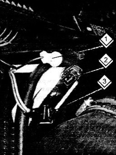
The coolant temperature sensor (2) is located on the left end face of the cylinder head below the coolant pipe (1). In the figure, the plug (3) is shown disconnected.
Disconnect the connector on the sensor from the left end of the cylinder head.
Connect an ohmmeter to both sensor contacts and measure the resistance.
Check that the resistance value corresponds to the coolant temperature.
If the values correspond to the coolant temperature, then the sensor is OK.
Lambda control check
To perform the check, the idle speed must be adjusted correctly, you need to make sure that there are no leaks in the exhaust system and the temperature sensor is working properly.
To check the operation of the lambda probe heating, disconnect the plug on the probe.
Using a test lamp, check if there is voltage between the red/white wire contact and ground.
If not, find the broken wire using the electrical diagram.
Then you should interrogate the memory of the self-diagnostic system.
For the measurement described below, a special cable is used in the workshop, with which you can connect to the pressure regulator wires with the plug inserted.
Connect the measuring cable between the pressure regulator and the plug, connect the ammeter.
1 Black wire to the control unit
2 Plug to mounting block
3 Plug to the lambda probe with black, white and brown wires.
Start the warm engine and let it idle for at least 2 minutes.
Read and record the current value.
Clamp the engine crankcase ventilation hose. The current should drop.
If not, you should disconnect the lambda probe plug.
The black wire going to the control unit should be shorted to ground for about 2 seconds.
If the current value changes, then the lambda probe is faulty.
If the current remains unchanged, the fault may be in the Motronic control unit. It is checked in the workshop.
(Content source: the specified website: Audimanual.ru)