
Table of contents: Air flow sensor (Motronic 3.2) ↓ Air flow sensor (KE… ↓ Throttle potentiometer (Motronic… ↓ Intake Manifold Air Temperature… ↓ Throttle Positioning Module… ↓ Vehicle speed sensor (Motronic 3.2) ↓ Coolant temperature sensor (all… ↓ Engine speed sensor (all systems) ↓ Throttle body (all systems) ↓ Injectors and fuel rail (Motronic… ↓ Fuel pressure regulator (Motronic… ↓ Hall sensor (Motronic 3.2) ↓ Oxygen sensor (all systems) ↓ Electronic control unit ↓ Fuel injectors (KE) ↓
Air flow sensor (Motronic 3.2)
Air flow sensor location (aDR engine)
On the ADR engine, the air flow sensor is mounted on the top cover of the air filter.
Removal
1. Remove the cover.
2. Disconnect the air hose from the sensor (aDR engine).
3. Disconnect the sensor connection connector (aDR engine).
4. Loosen the mounting screws and remove the sensor.
Installation
Installation is carried out in the reverse order of removal.
Air flow sensor (KE Motronic/Jetronic)
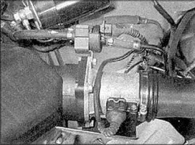
Air Flow Sensor Components on ACE Engine
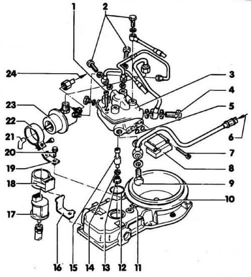
- 1. Mounting screw
- 2. Banjo connection bolt
- 3. Fuel distributor
- 4. Banjo connection bolt
- 5. Sealing rings
- 6. Fuel supply pipe
- 7. Mounting screw
- 8. Pressure regulator
- 9. Banjo connection bolt
- 10. Air flow sensor
- 11. Plug
- 12. Sealing ring
- 13. Locking screw
- 14. Sealing ring
- 15. Plunger
- 16. Mounting bracket
- 17. Blow-off valve
- 18. Fastening
- 19. Mounting bracket
- 20. Screw
- 21. Ventilation hose
- 22. Mounting bracket
- 23. Diaphragm pressure regulator
- 24. Return fuel line
Removal
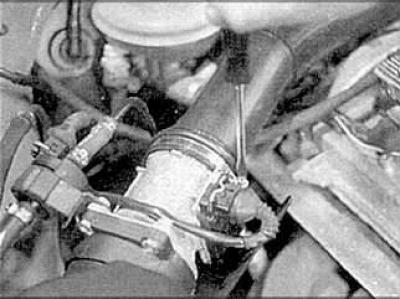
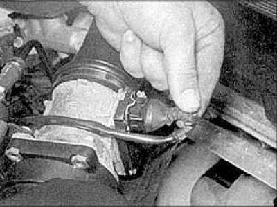
1. Mark the fuel lines and disconnect them from the fuel distributor.
2. Remove the air intake pipe.
3. Loosen the mounting bolts and remove the sensor.
Installation
Installation is carried out in the reverse order of removal.
Throttle potentiometer (Motronic 3.2) or throttle position sensor (KE Motronic/Jetronic)
Removal
1. Disconnect the connection connector.
2. Loosen the mounting screws and remove the potentiometer or sensor.
Installation
Installation is carried out in the reverse order of removal.
Intake Manifold Air Temperature Sensor (Motronic 3.2)
Removal
1. Disconnect the connection connector.
2. Loosen the mounting bolts and remove the sensor.
Installation
Installation is carried out in the reverse order of removal.
Throttle Positioning Module (Motronic 3.2)
Removal and installation of the module is carried out in the same way as for the throttle potentiometer.
Vehicle speed sensor (Motronic 3.2)
The sensor is installed in the speedometer unit, and to replace it, you need to replace the speedometer.
Coolant temperature sensor (all systems)
Removal
1. Drain approximately one-quarter of the coolant from the engine.
2. Disconnect the connector of the corresponding sensor and unscrew it from the socket.
Installation
Installation is carried out in the reverse order of removal.
Engine speed sensor (all systems)
Removal
1. Disconnect the sensor connection connector.
2. Loosen the mounting bolt and remove the sensor.
Installation
Installation is carried out in the reverse order of removal.
Throttle body (all systems)
Removal
1. Disconnect the accelerator cable.
2. Disconnect the connection connectors, vacuum and air hoses.
3. Remove the mounting bolts and remove the throttle body.
Installation
Installation is carried out in the reverse order of removal.
Injectors and fuel rail (Motronic 3.2)
Removal
1. Disconnect the vacuum hose, fuel lines and hoses from the fuel rail.
2. Disconnect the injector and Hall sensor connectors.
3. Loosen the mounting bolts and remove the fuel manifold.
Installation
Installation is carried out in the reverse order of removal.
Fuel pressure regulator (Motronic 3.2)
Removal
1. Disconnect the vacuum hose from the regulator.
2. Remove the retaining clip and remove the regulator from the fuel rail.
Installation
Installation is carried out in the reverse order of removal.
Hall sensor (Motronic 3.2)
Removal
1. Disconnect the sensor connection connector.
2. Loosen the mounting bolts and remove the sensor.
Installation
Installation is carried out in the reverse order of removal.
Oxygen sensor (all systems)
Oxygen sensor location (aDR engine)
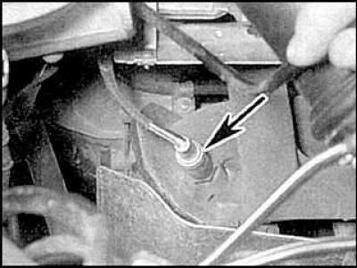
Removal
Disconnect the sensor connection connector and unscrew the sensor from the exhaust manifold.
Installation
Installation is carried out in the reverse order of removal.
Electronic control unit
Removal
1. Remove the trim panels.
2. Loosen the mounting screws and remove the electronic control unit covers.
3. Loosen the mounting screws and remove the electronic control unit, disconnecting the connection connector.
Installation
Installation is carried out in the reverse order of removal.
Fuel injectors (KE)
Removal
1. Disconnect the injector connection connectors.
2. Remove the cooling hose if necessary.
3. Remove the fuel manifold (if necessary), unscrew the connection nuts and disconnect the fuel pipes.
4. Remove the injectors.
Installation
Installation is carried out in the reverse order of removal.
Material republished from the website AUDImanual