
Table of contents: Mass Air Flow Sensor (MAF) ↓ Throttle position sensor (TPS or… ↓ Intake Air Temperature Sensor ↓ Idle speed control valve ↓ Vehicle speed sensor ↓ Coolant temperature sensor ↓ Engine speed sensor ↓ Throttle body ↓ Fuel injectors and fuel rail ↓ Fuel pressure regulator ↓ Hall sensor ↓ Oxygen sensor (Lambda probe) ↓ Electronic control unit (ECU) ↓
Note: Before you begin, please read the warnings in paragraph 1. The ignition must be off at all times.
Mass Air Flow Sensor (MAF)
Removal
1. DMR8 is installed on the upper cover of the air filter housing. Unhook the latches and remove the upper cover from the housing.
2. Loosen the clamp and disconnect the air duct from the MAF.
3. Disconnect the wiring connector from the sensor.
4. Loosen the mounting screws and remove the sensor. Remove the gasket.
Installation
5. Installation is the reverse procedure. Install a new gasket or sealing ring (what is provided).
Throttle position sensor (TPS or throttle potentiometer)
Note: The TPS is matched to the throttle body at the factory and is not available as a spare part. A faulty TPS requires replacement of the entire throttle body.
Removal
6. Disconnect the wiring connector from the sensor.
7. Loosen the mounting screws and remove the sensor from the throttle body. Remove the sealing ring.
Installation
8. Installation is the reverse procedure. Please note the following.
- a) Replace the sealing ring if necessary.
- b) Correctly align the sensor with the valve axis.
- c) On models with automatic transmission, the sensor must be matched with the automatic transmission control unit - this requires the use of specialized equipment. Contact your dealer.
Intake Air Temperature Sensor
Removal
9. If present, the sensor is screwed into the intake manifold near the throttle body.
10. Disconnect the wiring connector from the sensor.
11. Unscrew the bolts and remove the sensor from the manifold.
Installation
12. Installation is the reverse procedure. Be sure to ensure that the threaded connection is tightened to the correct torque.
Idle speed control valve
Removal and installation
13. The idle speed controller is built into the multi-function throttle body, which includes a throttle potentiometer and an idle speed sensor/switch. In addition to controlling the engine idle speed, the controller acts as a damper when the throttle valve is closed.
14. The removal and installation procedures are similar to those above for the throttle potentiometer. Note that when power is disconnected from the regulator, the throttle valve automatically moves to the base position.
15. After installing the regulator, it is necessary to perform its activation procedure, which requires the use of specialized equipment VAG 1551 or 1552. Contact your Audi/VAG dealer for assistance.
Vehicle speed sensor
Removal and installation
16. If provided, the sensor is integrated into the speedometer and its signal is processed by the Motronic control unit. The signal is used to stabilize idle speed and to minimize shocks when shifting gears. Sensor faults can be detected using Audi/VA diagnostic equipment: If necessary, replace the entire speedometer unit on the front panel - see chapter 12.
Coolant temperature sensor
Removal
17. The sensor is installed on all engines in the rear part of the cylinder head.
18. Drain approximately a quarter of the coolant from the engine as described chapter 1A.
19. Disconnect the wiring from the sensor.
20. Carefully unscrew the sensor or remove the retainer and then the sensor. Remove the sealing washer.
Installation
21. Installation is the reverse procedure. Install a new sealing washer. If provided, tighten the sensor securely. Top up the coolant as described in chapter 1A.
Engine speed sensor
Removal
22. The sensor is installed in the rear left part of the cylinder block, closer to the mating plane with the bell, behind the oil filter. If necessary, drain the engine oil and remove the oil filter with the oil cooler as described in chapter 1 to improve access.
23. Disconnect the electrical connector from the sensor.
24. Loosen the mounting bolt and remove the sensor from the cylinder block.
Installation
25. Installation - reverse procedure.
Throttle body
Removal
26. On models with an accelerator cable, disconnect it from the throttle control lever as described in paragraph 3.
27. Loosen the clamps and disconnect the intake air duct from the throttle body.
28. Disconnect the wiring connector from the TPS housing.
29. Disconnect the vacuum hose from the throttle body inlet and, if necessary, free the wiring from its fasteners.
30. Remove the through bolts and throttle body from the intake manifold. Remove and discard the gasket.
31. If necessary, remove the throttle potentiometer - see the corresponding subparagraph.
Installation
32. Installation is the reverse procedure, please note the following:
- a) Install a new gasket between the housing and the intake manifold.
- b) Make sure that the vacuum hoses and electrical connectors are securely connected.
- c) If necessary, adjust the accelerator cable - see paragraph 3.
Fuel injectors and fuel rail
Removal
33. Disconnect the ground cable from the battery as described in chapter 5A.
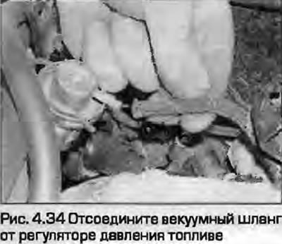
34. Disconnect the vacuum hose from the fuel pressure regulator on the fuel rail (Fig. 4.34).
35. Temporarily remove the fuel tank filler cap and reinstall it to relieve any pressure in the tank.
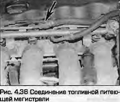
36. Place a rag around the connection of the fuel supply line to the fuel rail (Fig. 4.36). Place a suitable container underneath to collect the fuel. Loosen the connection nut, holding the bolt with another open-end wrench, and drain the fuel into the container underneath. Remove the rag.
37. Unscrew the return line connection and disconnect its tube from the ramp.
38. Disconnect the wiring from all injectors. Label the wiring to avoid confusion during installation.
39. On ADP and AEB engines, disconnect the wiring from the Hall sensor.
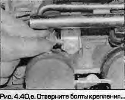
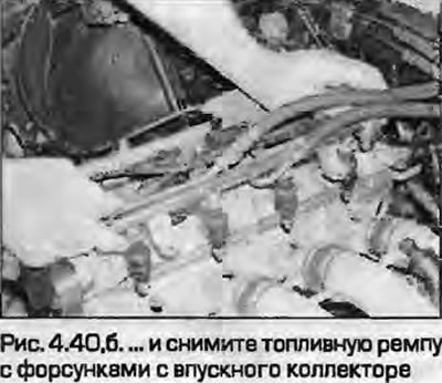
40. Loosen the mounting bolts, then carefully remove the fuel rail together with the injectors from the intake manifold (fig. 4.40, a, b).
 |
 |
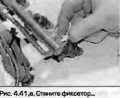
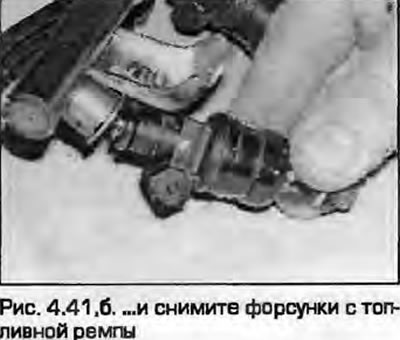
41. Having installed the unit on the workbench, tighten the fasteners and remove the injectors from the fuel rail. Remove the sealing rings (fig. 4.41, a, b).
 |
 |
Installation
42. Installation is the reverse procedure. Please note the following.
- a) Replace the injector sealing rings with new ones, lightly lubricate them with engine oil before installation to facilitate installation. When installing the front sealing ring, do not remove the plastic cover from the injector, leave it in place and put the ring through it.
- b) Make sure the injectors are securely fastened.
- c) Connect the fuel lines correctly. Check the condition of the sealing washers and replace them if necessary.
- d) Check the reliability of vacuum and electrical connections.
- d) Connect the battery - see chapter 5A.
- e) Finally, start the engine and check for leaks.
Fuel pressure regulator
Removal
43. If necessary, remove the top engine cover and relieve the pressure in the fuel system - see paragraph 9.
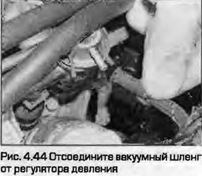
44. Disconnect the vacuum hose from the pressure regulator (Fig. 4.44).
45. Place a rag under the regulator to collect fuel.
46. Pull out the spring retainer and remove the regulator from the fuel rail. Remove the sealing rings.
Installation
47. Installation - reverse procedure, install new sealing rings.
Hall sensor
Note: This section does not cover removing the Hall sensor on an ADP engine, as it is located in the distributor.
Removal
48. Remove the outer timing belt cover as described in paragraph 4 of chapter 2A.
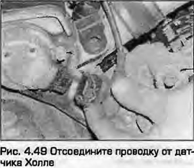
49. Release the retainer and disconnect the wiring connector from the Hall sensor (Fig. 4.49).
50. Loosen the mounting bolts and remove the sensor from the front of the cylinder head. Remove the gasket.
Installation
51. Installation - reverse procedure. Replace the gasket. Tighten the mounting bolts securely.
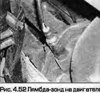
Oxygen sensor (Lambda probe)
Removal
52. On all engines except AEB and AJL (turbocharged) the sensor is installed in the exhaust manifold to the right of the engine (Fig. 4.52). On AEB and AJL engines, the sensor is installed in the upper part of the catalytic converter, which is mounted at the rear of the turbocharger to the right of the engine.
53. The sensor wiring connector is located on the left side of the engine shield, under the expansion tank of the cooling system. Unscrew the tank mounting screws and disconnect the wiring, move the tank to the side. Do not disconnect the hoses. Disconnect the sensor wiring from all fasteners.
54. Unscrew the sensor and remove it carefully without damaging the tip.
Note: If there is a special head with a slot, the wire from the sensor can be disconnected when unscrewing.
Installation
55. Apply non-stick lubricant to the threads, but do not coat the sensor tip with it.
Note: A new sensor may already have grease applied to its threads.
56. Screw in the sensor and tighten it to the specified torque.
57. Connect the wiring and secure with plastic ties.
Electronic control unit (ECU)
Warning: Wait at least a few seconds after switching off the ignition before disconnecting the connector. When disconnecting the connector, all set data is erased, but possible fault codes are stored in the memory. After connecting the connector, it is necessary to program the basic settings, which requires specialized Audi/VAG equipment. When starting the ECU, you must also enter the identification code on the unit into the immobilizer memory. Contact your dealer for assistance.
Removal
58. The electronic control unit is installed on the engine shield at the rear of the engine compartment. On right-hand drive models it is located on the right, on left-hand drive models it is located on the left.
59. Disconnect the ground wire from the fan as described in chapter 5A.
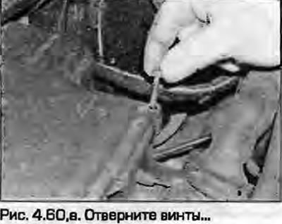
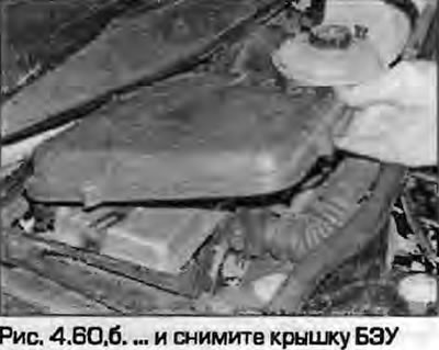
60. Loosen the screws and remove the cover (Fig. 4.60).
 |
 |
Note: On early left-hand drive models there is a hole in the cover panel in front of the windshield to access the mounting bolt, on later models there is no hole - the panel must be removed.
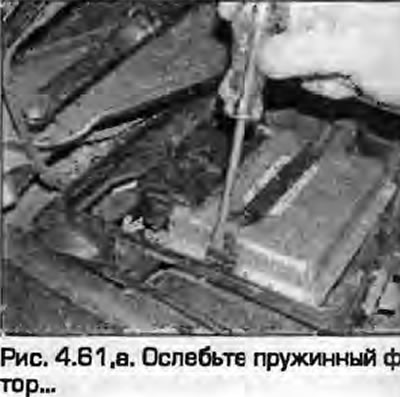
61. Use a screwdriver to release the spring clip and lift the ECU upwards (Fig. 4.61).
 |
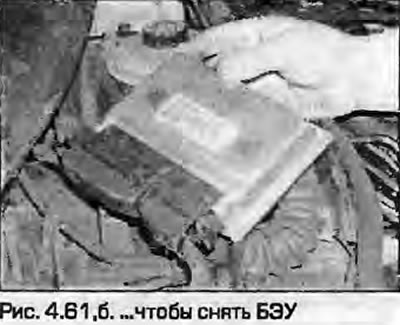 |
62. Release the retainer and disconnect the wiring connector from the unit.
Warning: After turning off the ignition, wait at least 30 seconds before disconnecting the connector.
63. Remove the block from the engine shield.
Installation
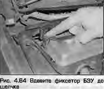
64. Installation - reverse procedure. Press the lock until it clicks (Fig. 4.64). Connect the battery - see chapter 5A.
(This article was previously published on the resource «AUDIMANUAL.RU»)