
Table of contents: General information ↓ Precautionary measures ↓
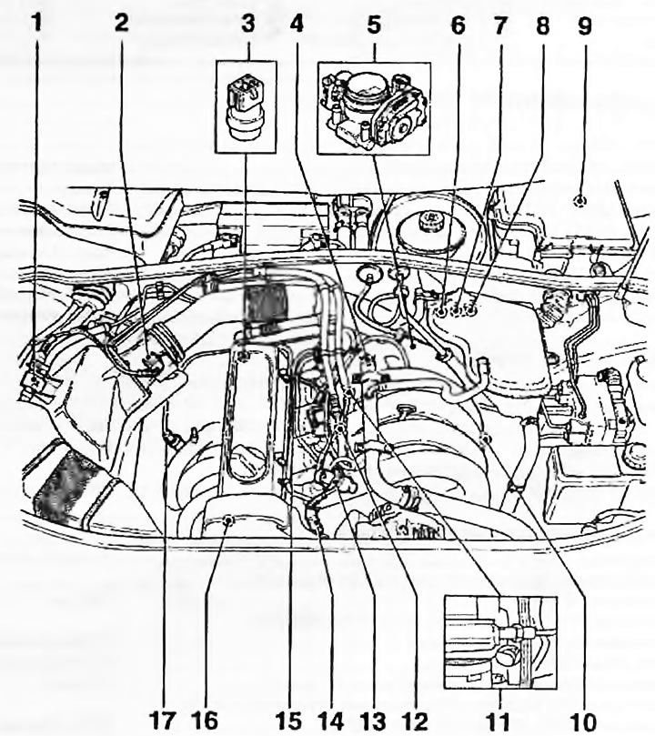
Fig. 1.1, a. Components of the Motronlc system on the AHL engine: 1. Carbon adsorber purge valve; 2. MAF; 3. Coolant temperature sensor; 4. High voltage terminal of the ignition coil; 5. Throttle body; 6. Oxygen sensor wiring connector; 7. Engine speed sensor wiring connector; 8. Knock sensor wiring connector; 9. BEU; 10. Intake air temperature sensor; 12. Knock sensor; 13. Fuel pressure regulator; 14. Hall sensor wiring; 15. Nozzles; 16. Hall sensor; 17. Oxygen sensor
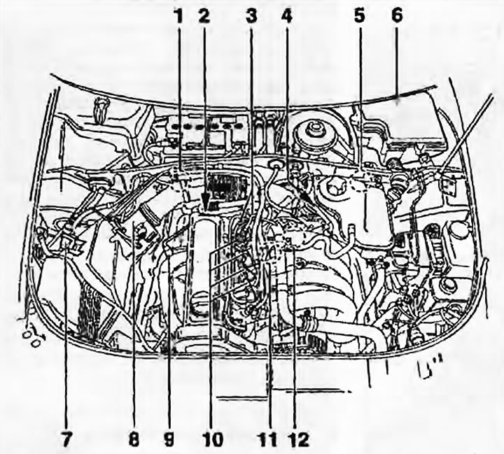
Fig. 1.1, b. Components of the Motronic system on ADP engines: 1. Ignition coil; 2. Coolant temperature sensor; 3. Distributor with Hall sensor; 4. TPS; 5. Oxygen sensor, RPM sensor and knock sensor wiring connectors; 6. BEU; 7. Carbon adsorber electromagnetic valve; 8. MAF; 9. Oxygen sensor; 10. Nozzles; 11. Knock sensor; 12. Engine speed sensor
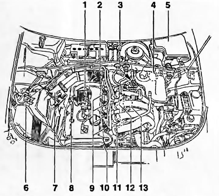
Fig. 1.1, c. Components of the Motronic system on ADR engines: 1. Ignition coils and high-voltage wires; 2. Coolant temperature sensor; 3. TPS; 4. Wiring connectors for the oxygen sensor, speed sensor, knock sensors 1 and 2; 5. BEU; 6. Carbon adsorber electromagnetic valve; 7. MAF; 8. Oxygen sensor; 9. Nozzles; 10. Hall sensor; 11. Knock sensor 1; 12. Knock sensor 2; 13. Engine speed sensor
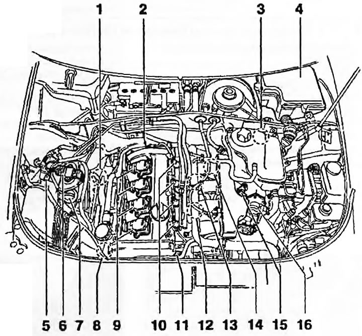
Fig. 1.1, d. Components of the Motronic system on the AEB engine: 1. Oxygen sensor; 2. Coolant temperature sensor; 3. Wiring connectors for the oxygen sensor, engine speed sensor, knock sensors 1 and 2; 4. BEU; 5. Carbon adsorber electromagnetic valve; 6. Ignition supply; 7. MAF; 8. Boost pressure control solenoid valve; 9. Ignition coils; 10. Nozzles; 11. Hall sensor; 12. Knock sensor 1; 13. Knock sensor 2; 14. Engine speed sensor; 15. Intake air temperature sensor; 16. TPS
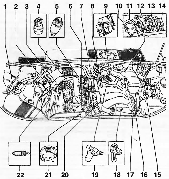
Fig. 1.1, d. Components of the Motronic system on the APT engine: 1. Carbon adsorber electromagnetic valve; 2. MAF; 3. Ignition coils and high-voltage wires; 4. Coolant temperature sensor; 5. Camshaft control valve; 6. Nozzles; 7. Fuel pressure regulator; 8. Knock sensor 2; 9. TPS; 10. Oxygen sensor wiring connector; 11. Oil sensor wiring connector; 12. Speed sensor wiring connector; 13. Knock sensor 2 wiring connector; 14. Knock sensor wiring connector 1; 15. BEU; 16. Intake manifold vacuum control unit; 17. Intake manifold control valve; 18. Intake air temperature sensor; 19. Engine speed sensor; 20. Knock sensor 1; 21. Hall sensor; 22. Oxygen sensor
General information
The Bosch and Simos multi-point fuel injection systems described in this chapter are systems that control both fuel injection and ignition (fig. 1.1, a-d). This chapter describes only the components of the injection system, the components of the ignition system are described in chapter 5B.
The fuel system consists of a fuel tank (under the rear of the car. with an electric fuel pump built into the tank), fuel filter, throttle body, air mass sensor (MAF), fuel rail with four injectors, fuel pressure regulator, supply and return lines, electronic control unit with sensors and actuators and wiring. The composition of the components depends on the type of system used - see the corresponding paragraph.
AEB and AJL engines are equipped with a turbocharger.
The MAF is mounted between the air filter outlet and the throttle body. The fuel pump supplies fuel under pressure to the fuel rail and then to four electronically controlled injectors. The injection duration is determined by the ECU, which opens and closes the injectors according to commands from it.
The fuel pump delivers fuel through a replaceable fuel filter via the fuel line (fuel supply line) to the fuel rail, the pressure in which is maintained constant by a pressure regulator.
The pressure regulator releases excess fuel into the return fuel line (return fuel line). The constant fuel flow system ensures a reduction in fuel temperature and prevents vapor lock.
The BEU provides fuel enrichment during start-up and warm-up, idle speed control and exhaust gas composition control. Partially idle speed is determined by the electronic throttle position module mounted on the side of the throttle body and partially by the ignition system. There is no manual adjustment of idle speed.
Air enters the engine through a replaceable paper air filter.
The oxygen content in the exhaust gases is monitored by the ECU using an oxygen sensor (lambda probe) in the exhaust manifold. The ECU uses the information received from the sensor to regulate the fuel-air mixture ratio. Manual adjustment of the CO content in the exhaust gases is not provided. A catalytic converter is built into the exhaust system of all models, except the earliest ones. The fuel vapor recovery system is installed on all models. The carbon adsorber is purged by commands from the ECU - the system is described in detail in chapter 4B.
Troubleshooting the system is only possible with specialized diagnostic equipment. If a fault occurs in the system, contact your Audt/VAG dealer for assistance. If a fault is found, removal and installation of the faulty unit is described in detail in the following paragraphs.
Note: In this chapter, vehicles are identified according to engine model code and engine capacity - a list of engines is provided in chapter 2A.
Precautionary measures
Caution! Many of the procedures in this chapter require the removal of fuel lines and connections that could cause fuel spills. Before performing any work on the fuel system, refer to the warnings given in the section "Safety first!" at the beginning of this manual and follow them strictly. Gasoline is a very dangerous volatile liquid, safety precautions when working with it should not be ignored.
Note: Residual pressure will remain in the fuel lines for a long time after the vehicle has been used. Before disconnecting any fuel line, first relieve the pressure in the system as described in paragraph 9.