
Table of contents: Removal ↓ Installation ↓
Note: Before starting work, read the warnings contained in paragraph 7. A special Audi/VAG tool is required to remove the inner section of the damper housing.
Removal
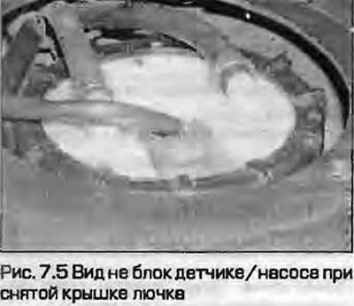
1. The pump and sensor are combined into one unit installed in the fuel tank. Access to it is possible through a hatch in the floor of the luggage compartment. Removal implies contact of the tank contents with the atmosphere - take special fire safety measures. The surrounding area around the car should be well ventilated so that fuel vapors do not accumulate. If possible, remove the unit with the tank as empty as possible or pump out the fuel into a suitable canister.
2. Relieve the pressure in the fuel system as described in paragraph 9.
3. Position the vehicle horizontally. Disconnect the ground cable from the battery as described in chapter 5A.
4. As described in chapter 11, remove the trim from the luggage compartment floor.
5. Loosen the screws securing the hatch and remove it from the floor (Fig. 7.5).
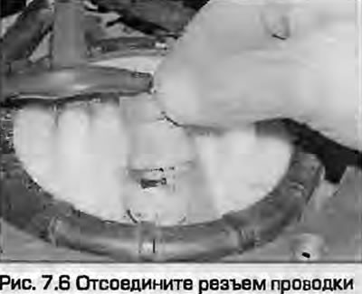
6. Disconnect the electrical connector from the pump/sensor assembly (Fig. 7.6).
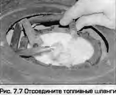
7. Place a rag under the fuel collection hoses. Loosen the clamps and remove the feed and return hoses (Fig. 7.7). Label the hoses to avoid confusion during installation. Release the tubes from the fasteners on the support ring.
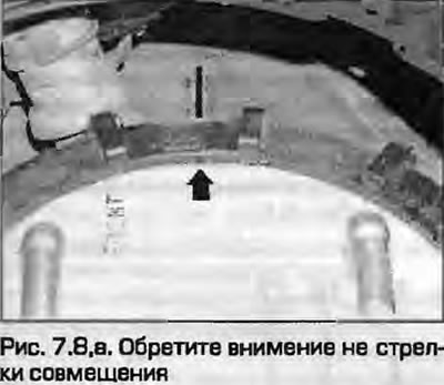
8. Remember the direction of the arrows and the ring, unscrew the plastic ring of the block fastening in the back. For this operation, Audi/VAG mechanics have a special tool. However, for this it is enough to insert two screwdrivers into the slots of the ring and cross them. You can use a large adjustable wrench "dog" (fig. 7.8, a, b).
 |
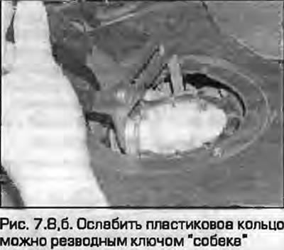 |
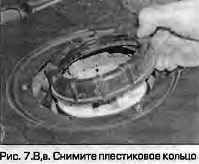
9. Remove the flange and seal from the opening in the tank.
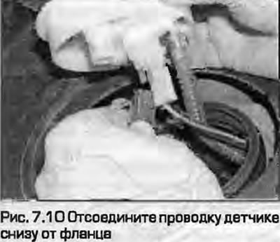
10. Disconnect the sensor wiring and release it from the flange (Fig. 7.10).
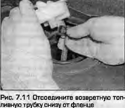
11. Pull off the casing, disconnect the return fuel pipe from the bottom of the flange (Fig. 7.11).
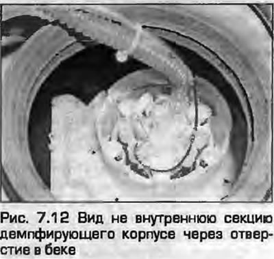
12. Turn the inner section of the damper housing counterclockwise by approximately 15° and remove it together with the fuel pump (Fig. 7.12). Audi mechanics use a special tool for this, aligning it with the cutouts on the top of the pump - it is strongly recommended to use it. You can also make a homemade one, but the plastic is very fragile - it can be broken. If the pump is to be replaced, drain all the fuel from the old block. The flange can be removed from the pump by loosening the clamp and disconnecting the intermediate feed pipe. Remember the way it is installed in order to reassemble everything correctly.
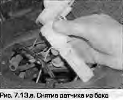
13. To remove the sensor, press the latch on the side of the damper housing inside the tank. Carefully remove the sensor (fig. 7.13, a, b).
 |
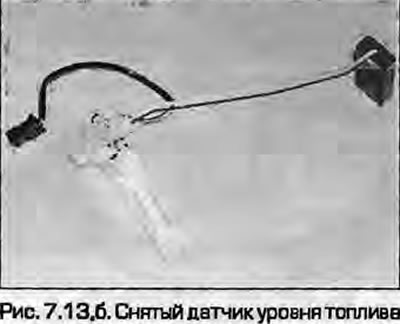 |
14. Inspect the sensor float - there should be no holes in it and there should be no fuel gurgling in it. Replace a damaged float. A damaged seal of the hole in the tank should also be replaced. Inspect the runner and rheostat of the sensor - there should be no breaks in the conductor. Remove any possible dirt from the rheostat
Installation
15. Insert the sensor into the damping housing, press until the lock snaps into place.
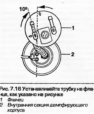
16. If the flange was removed from the pump, attach the intermediate feed pipe and tighten the clamp (Fig. 7.16).
17. Insert the inner damping housing with the pump into the outer housing so that the protrusion on the upper edge aligns with the first mark on the housing. Using an open-end wrench, push the pump housing down and turn it clockwise until it aligns with the second mark on the housing.
18. Attach the fuel return pipe to the bottom of the flange.
19. Attach the fuel sensor wiring to the inside of the flange and attach it to the bottom of the flange. The wiring should be wrapped once around the fuel return line.
20. Lubricate the new rubber seal with clean fuel, install it on the flange, install the flange into the fuel tank hole.
21. Install the support ring, then screw and tighten the plastic one. To ensure that the arrows align when tightening the ring, turn the flange slightly counterclockwise while tightening the ring.
22. Connect the fuel hoses and tighten the clamps.
23. Connect the wiring connector to the pump/sensor unit.
24. Install the hatch and tighten the screws that secure it.
25. Install the trim on the luggage compartment floor.
26. Connect the battery as described in chapter 5A.