
Warning: The power system is under pressure. Before disconnecting the elements of the system, it is necessary to relieve the pressure in the system. To do this, cover the disconnection point with a clean cloth and, being careful, slowly unscrew the connection.
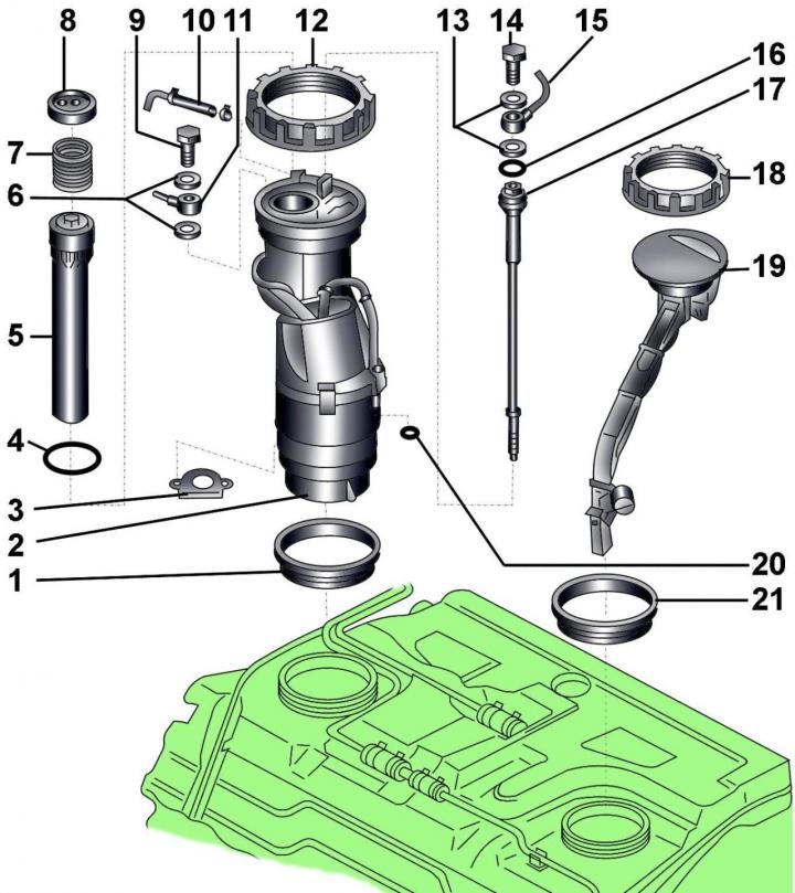
Pic. 4.1–9. Fuel Pump / Fuel Level Sensor: 1 - gasket; 2 – a casing of the fuel pump; 3 - plug, 4 - sealing ring; 5 – fuel level sensor; 6 - gaskets; 7 - spring; 8 – fuel level sensor cover; 9 - hollow bolt, 23 Nm; 10 - fuel return pipe; 11 - supply pipe to the fuel filter; 12 - connecting nut, 70 Nm; 13 - gaskets; 14 - hollow bolt, 13 Nm; 15 - supply pipe; 16 - sealing ring; 17 - tubular bolt, 20 Nm; 18 - connecting nut, 60 Nm; 19 - fuel level sensor G169; 20 - sealing ring; 21 - gasket
On models with petrol engines, the fuel pump together with the fuel level sensor (pic. 4.1–9) installed in the fuel tank.
The design of the fuel level sensor includes a potentiometer and an associated float. When the amount of fuel decreases, the float drops, the resistance of the potentiometer increases, the voltage at the fuel gauge located in the instrument cluster decreases.
Note: New gaskets, O-rings and plug must be used when installing.
Withdrawal
Before disconnecting the battery, find out if you have a radio activation code.
Turn off the ignition and disconnect the wire «masses» from the battery.
Remove the fuel pump/fuel gauge covers located on the right side under the trunk carpet.
Using the special tool 2012A, unscrew the cover 8 (see fig. 4.1–9) fuel level sensor, turning it clockwise, remove cover 8 and spring 7 located under the cover.
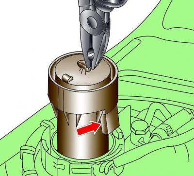
Pic. 4.1–10. Fuel Level Sensor Removal and Electrical Connector Location
Using pliers, remove the fuel level sensor 5 and disconnect the electrical connector from it (pic. 4.1–10).
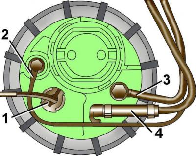
Pic. 4.1–11. Electrical connector location (1), tubing auxiliary (2), filing (3) and return (4) fuel
Disconnect the electrical connector 1 from the fuel level sensor housing (pic. 4.1–11).
Unscrew the hollow bolt and disconnect the auxiliary tube 2.
Unscrew the hollow bolt and disconnect the fuel supply pipe 3.
Disconnect the fuel return pipe 4.
Using special tool 3242, unscrew union nut 12 (see fig. 4.1–9) securing the fuel level sensor/fuel pump assembly.
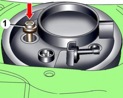
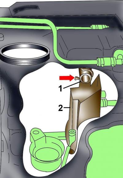
Pic. 4.1–12. Bolt location and direction (1)
Unscrew bolt 1 a few turns, but do not unscrew it completely (pic. 4.1–12).
Push down on the bolt to separate the fuel level sensor/fuel pump from the fuel tank interconnect board.
Completely unscrew the bolt.
Lift up the fuel level sensor/fuel pump and remove the gasket.
To remove the fuel level sensor/fuel pump, move it up by turning it clockwise.
Installation
Install in the reverse order of removal.
Pic. 4.1–13. tube mount (1) fuel supply for the latch on the connecting board (2) fuel tank
Before installation, check that the fuel supply pipe is fixed with a retainer on the connection board (pic. 4.1–13). To do this, you can use a light bulb and a mirror. If the tube is not secured to the connection board, the fuel level sensor/fuel pump cannot be installed correctly and the connection board may be damaged during installation.
Replace the O-rings on the fuel gauge/fuel pump assembly.
Check that the fuel level sensor electrical connector is on top and does not fall into the fuel tank during installation.
Install the fuel level sensor/fuel pump as follows.
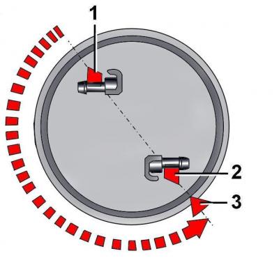
Pic. 4.1–14. Positions of the fuel level sensor / fuel pump during installation: 1 - initial position; 2 - final position; 3 - label
In the original position, the hose fitting must be located on the left side of the vehicle (pic. 4.1–14).
When installing the sensor in the fuel tank, turn it 180°counterclockwise, while the hose fitting should be located on the right side of the car, and marks 2 and 3 (see fig. 4.1–14) should match.
Press the fuel level sensor/fuel pump down, while the fuel supply tube of the pump will be pressed against the feed tube of the connection board.
The bolt should be easy to install and screw into the connection board without much effort.
After verifying that the fuel level sensor/fuel pump is installed correctly, lift it slightly and install a new seal in the fuel tank seat.
Reinstall the fuel gauge/fuel pump.
Install a new o-ring on the clamp bolt and check that the restrictor tube is located inside the bolt. Please note that the restrictor tube is not installed on all models.
Install and screw in the clamping bolt.
Using special tool 3242, tighten the fuel level sensor/fuel pump union nut to 70 Nm.
Tighten the bolt to 23 Nm.
Connect the electrical connector to the fuel level sensor housing (see fig. 4.1–11).
Connect the auxiliary fuel pipe and secure it with a hollow bolt with new o-rings (see fig. 4.1–11).
Connect the fuel supply pipe and secure it with a hollow bolt with new o-rings (see fig. 4.1–11).
Connect the fuel return pipe.
Use pliers to lower the fuel level sensor into place and connect the electrical connector to it (see fig. 4.1–10).
Install the spring and, using the 2012A special tool, screw the fuel level sensor cover in by turning it counterclockwise.
Connect wire «masses» to the battery.
Turn on radio and enter the code into it.
Visitor comments