
To determine the ignition timing, the control unit uses information stored in memory and information from sensors installed on the engine. The ignition system receives control signals from the Hall sensor or pulse sensor. Additionally, the control unit adjusts the ignition timing and, based on a signal from the knock sensor, which is sensitive to premature ignition, accordingly reduces the ignition advance angle.
Warnings: To avoid damaging semiconductor devices (diodes and transistors) when carrying out work on the ignition system, the following requirements must be met:
- do not disconnect the battery, alternator or any electrical connectors while the engine is running;
- when performing any work, remove the negative terminal from the battery;
- when performing electric welding work on a vehicle, turn off the generator and control unit;
- do not operate the engine with the generator disconnected from the electrical system.
Do not touch high-voltage wires with your hand or disconnect them while the engine is running or while the engine is cranking with the starter.
Disconnect ignition system wires and instrument wires only when the ignition is off.
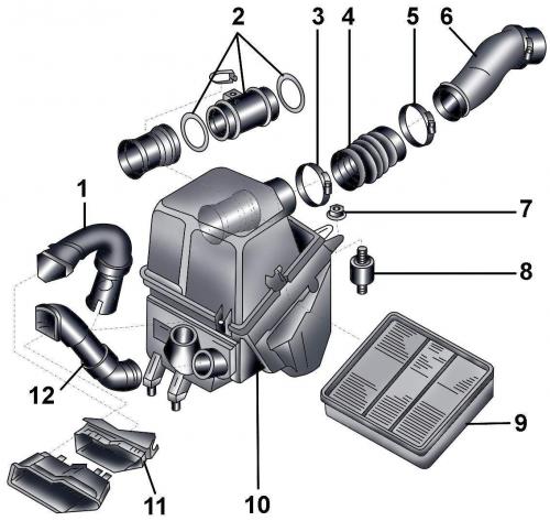
Fig. 4.1–22. Air filter: 1 – air duct; 2 – air flow meter G70; 3 – clamp; 4 – air intake duct; 5 – clamp; 6 – suction air duct; 7 – nut; 8 – rubber cushion; 9 – air filter element; 10 – air filter housing; 11, 12 – air duct
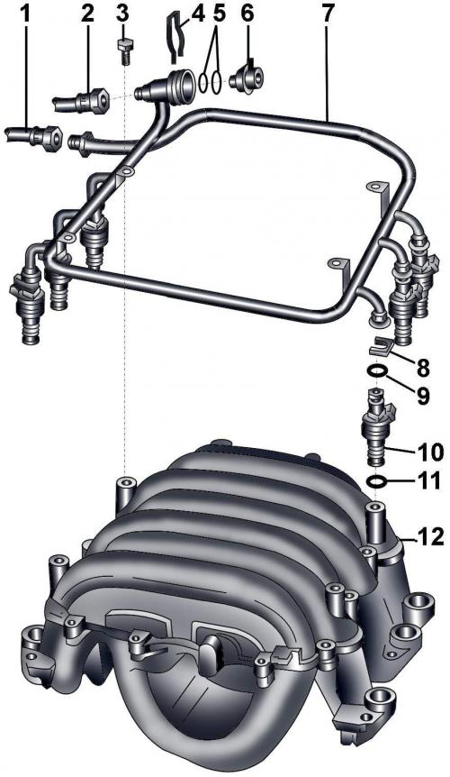
Fig. 4.1–23. Fuel line with injectors: 1 – fuel supply pipe from the fuel filter; 2 – fuel return pipe; 3 – bolt, 10 Nm; 4 – spring connector; 5 – sealing rings; 6 – fuel pressure regulator; 7 – fuel line; 8 – spring connector; 9 – sealing ring; 10 – nozzle; 11 – sealing ring; 12 – intake manifold
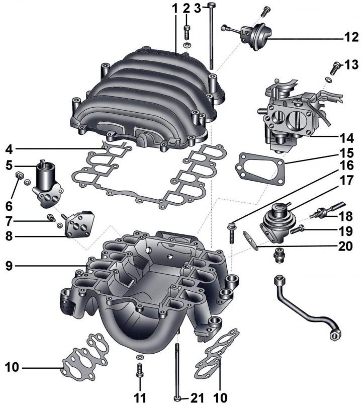
Fig. 4.1–24. Throttle body and intake manifold switching system: 1 – upper part of the intake manifold; 2 – bolt, 10 Nm; 3 – bolt, 20 Nm; 4 – gasket; 5 – idle speed stabilization valve N71; 6 – bolt, 10 Nm; 7 – bolt, 6 Nm; 8 – flange; 9 – intake manifold base; 10 – gasket; 11 – bolt, 10 Nm; 12 – vacuum chamber of the intake manifold switching valve; 13 – bolt, 20 Nm; 14 – throttle assembly; 15 – gasket; 16 – bolt, 20 Nm; 17 – mechanical valve of the exhaust gas recirculation system (EGR); 18 – EGR temperature sensor G98; 19 – bolt, 10 Nm; 20 – gasket; 21 – bolt, 10 Nm
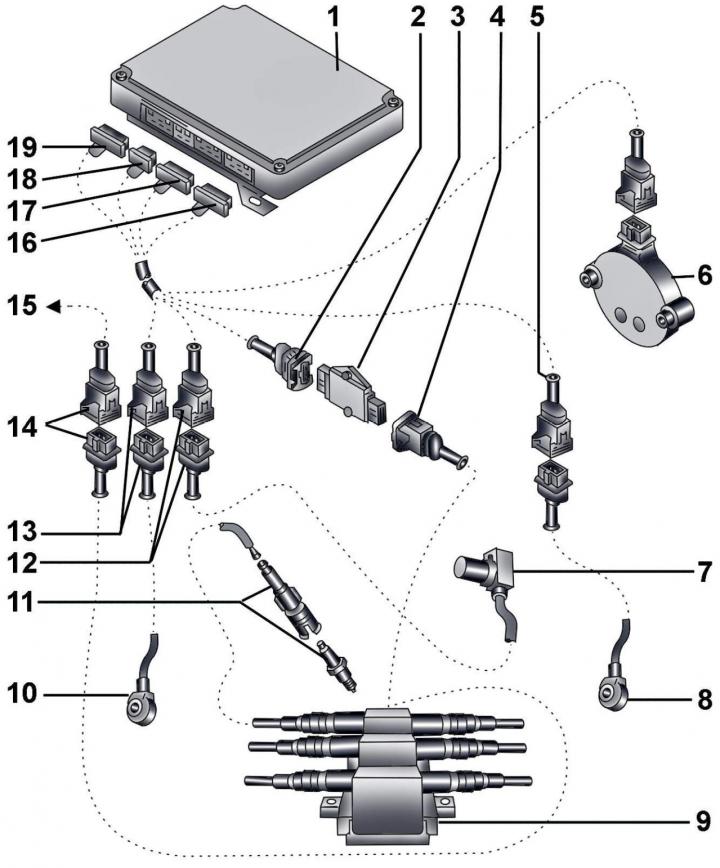
Fig. 4.1–25. Ignition system elements: 1 – Engine control unit J192; 2 - 4-pin brown electrical connector from the engine control unit; 3 – switch N122; 4 - 3-pin dark brown electrical connector from the primary windings of the ignition coils; 5 – 3-pin electrical connector from knock sensor G66; 6 – Hall sensor G40; 7 – ignition timing sensor G4 on the left cylinder block; 8 – Knock sensor G66; 9 – ignition coils N, N128, N158; 10 – Knock sensor G61; 11 – tip with spark plug; 12 – Electrical connector of the ignition timing sensor G4; 13 – Electrical connector of the knock sensor G61; 14 – Electrical connector for ignition coils; 15 – to connection S115 (located in the relay and fuse box); 16 - 16-pin electrical connector C brown; 17 – 20-pin electrical connector B red; 18 - 12-pin electrical connector A black; 19 – 16-pin electrical connector D green
The original article is posted on the resource audimanual