



Table of contents: Separating the center and rear… ↓ Alignment of exhaust system… ↓
The exhaust system is used to remove exhaust gases into the atmosphere, prevents them from entering the car interior even in minimal quantities, and reduces engine noise. In order for the exhaust system to function properly, it must be in good condition. The condition of the exhaust system also affects engine power and fuel consumption.
The exhaust system consists of an exhaust manifold, an exhaust pipe, a central and rear muffler, and a catalytic converter.
The exhaust system elements are connected using threaded connections or clamps.
Notes: Always replace gaskets and self-locking nuts.
After servicing or repairing the exhaust system, check that its components are installed freely, without tension, with sufficient clearance relative to the body elements.
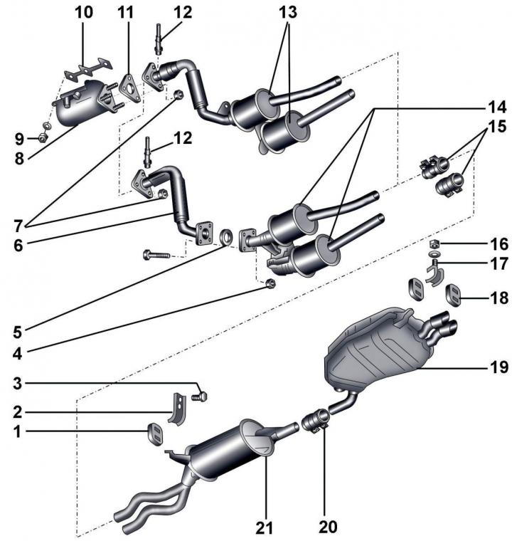
Fig. 4.2–1. Exhaust system of vehicles with six-cylinder gasoline engines: 1 – suspension system; 2 – bracket; 3 – bolt, 25 Nm; 4 – nut, 25 Nm; 5 – gasket, Nm; 6 – exhaust inlet pipe; 7 – nuts, 25 Nm; 8 – exhaust manifold; 9 – nut, 25 Nm; 10 – gasket; 11 – gasket; 12 – lambda sensor, 55 Nm; 13 – Neutralizers; 14 – Neutralizers; 15 – clamps; 16 – nut, 25 Nm; 17 – suspension bracket; 18 – exhaust system suspension; 19 – rear muffler; 20 – clamp; 21 – central muffler
When installing lambda sensor 12 (Fig. 4.2–1), it is necessary to apply high-temperature grease G 052 112 A3 to its threads.
The connecting element in the front exhaust pipe must not be bent more than 10°, otherwise it will be damaged.
When installing the exhaust system, the distance between the front pipes of the central muffler and the cross beam in a free state should be 43 mm.
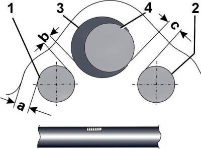
Fig. 4.2–2. Distance between exhaust pipes, propeller shaft and body elements of all-wheel drive vehicles: 1 – cross beam; 2 – exhaust pipes; 3 – cardan shaft of cars with manual transmission; 4 – cardan shaft of cars with automatic transmission; a = 22 mm; b = 10 mm (for manual transmission); c = 17 mm (for automatic transmission)
It is necessary to strictly maintain the distance between the exhaust pipes, the propeller shaft, the body elements and the rear suspension beam (Fig. 4.2–2 – 4.2–10).
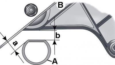
Fig. 4.2–3. Distance between exhaust pipes and rear suspension beam of cars: A – exhaust pipe; B – rear suspension beam; a = 27 mm; b = 20 mm
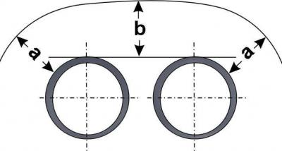
Fig. 4.2–4. Distance between exhaust pipes and elements of the rear bumper of cars: a – about 27 mm, should be the same on both sides; b = 20–22.5 mm
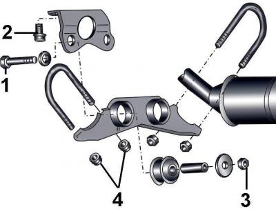
Fig. 4.2–5. Suspension elements of the front part of the front exhaust pipe to the body elements on early front-wheel drive vehicles with an automatic transmission: 1, 2 – bolts, 25 N·m; 3, 4 – self-locking nuts, 25 Nm
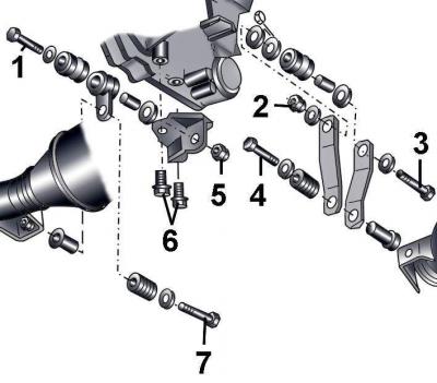
Fig. 4.2–6. Suspension elements of the front part of the front exhaust pipe to the body elements on front-wheel drive cars of late production with an automatic transmission: 1, 3, 4, 6, 7 – bolts, 25 N·m; 2, 5 – self-locking nuts, 25 Nm
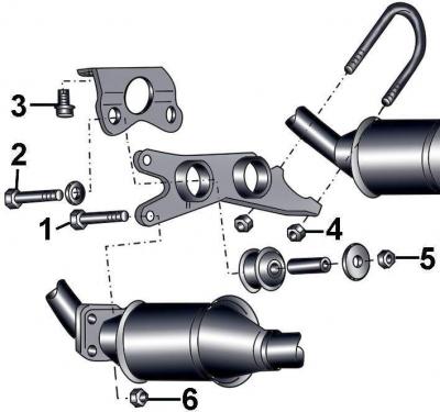
Fig. 4.2–7. Suspension elements of the front part of the front exhaust pipe to the body elements on all-wheel drive vehicles with an automatic transmission: 1, 2, 3 – bolts, 25 N·m; 4, 5, 6 – self-locking nuts, 25 Nm
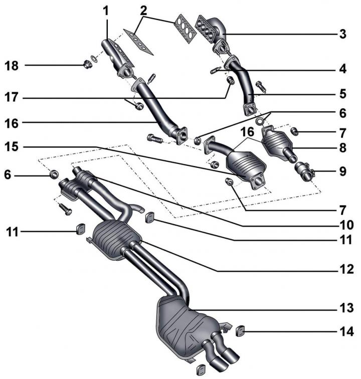
Fig. 4.2–8. Exhaust system of vehicles with eight-cylinder gasoline engines: 1 – left exhaust manifold; 2 – exhaust manifold gaskets; 3 – right exhaust manifold; 4 – lambda sensors, 50 Nm; 5 – exhaust inlet pipe; 6 – gaskets; 7 – nut, 25 Nm; 8 – right catalytic converter; 9 – double clamps (tighten the mounting bolts evenly to a torque of 40 Nm); 10 – front muffler; 11 – suspension system; 12 – central muffler; 13 – rear muffler; 14 – exhaust system suspension; 15 – left catalytic converter; 16 – exhaust inlet pipe; 17, 18 – nuts, 25 Nm
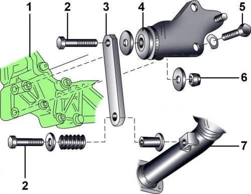
Fig. 4.2–9. Left catalytic converter suspension elements: 1 – gearbox; 2 – bolt, 25 Nm; 3 – earring; 4 – bracket; 5 – bolt, 25 Nm; 6 – nut, 25 Nm; 7 – front exhaust pipe
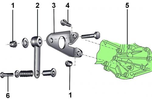
Fig. 4.2–10. Right catalytic converter suspension elements: 1 – nut, 25 N·m; 2 – earring; 3 – bracket; 4 – bolt, 25 Nm; 5 – gearbox; 6 – bolt, 25 Nm
On front-wheel drive and all-wheel drive vehicles, the suspension of the front part of the front exhaust pipe to the body elements differs in design (see Fig. 4.2–5).
To facilitate unscrewing, lubricate the nuts and bolts securing the exhaust system with Liqui Moly LM–508–ASC high-temperature paste.
Before re-installing the system elements, clean the joints with sandpaper to remove any remaining sealant and rust.
Separating the center and rear mufflers
If it is difficult to separate the exhaust pipes, use an autogenous welder to heat the joint and separate the pipes.
The rear and central mufflers are made as a single unit, but each of them can be replaced separately.
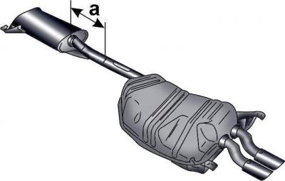
Fig. 4.2–11. Cutting location of the central and rear mufflers of cars with six-cylinder engines: a = 240 mm
To replace only one muffler, it is necessary to remove the central and rear muffler unit from the vehicle and cut them at a certain distance from the central muffler (Fig. 4.2–11 and 4.2–12).
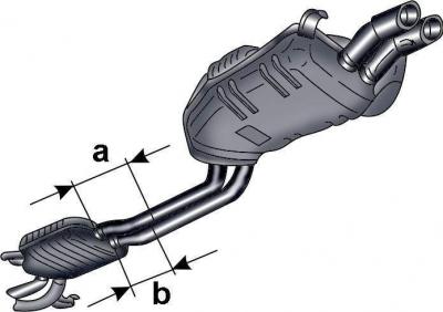
Fig. 4.2–12. Cutting location of the central and rear mufflers of cars with eight-cylinder engines: a = 240 mm; b = 200 mm
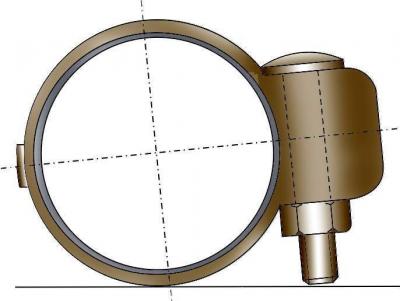
Fig. 4.2–13. Location of the clamp connecting the central and rear mufflers
Connect the new muffler section to the old one and install the clamp, positioning it so that the lower edge of the clamp mounting bolt is at the level of the muffler pipe (Fig. 4.2–13).
Alignment of exhaust system components
Align the exhaust system components on a cold engine.
Loosen the clamp mounting bolts.
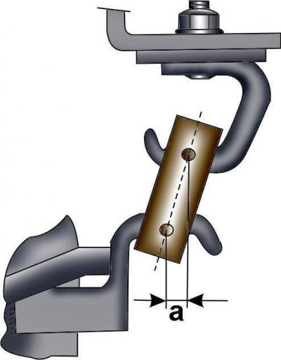
Fig. 4.2–14. Correct position of the rear muffler suspension: a = 10 mm
Move the exhaust system forward so that the rear muffler hanger is preloaded (Fig. 4.2–14).
Tighten the clamp mounting bolts to a torque of 40 Nm.