
Removal
Remove the lower dashboard cover on the driver's side.
Remove the transition plug from the engine compartment bulkhead in the driver's footwell.
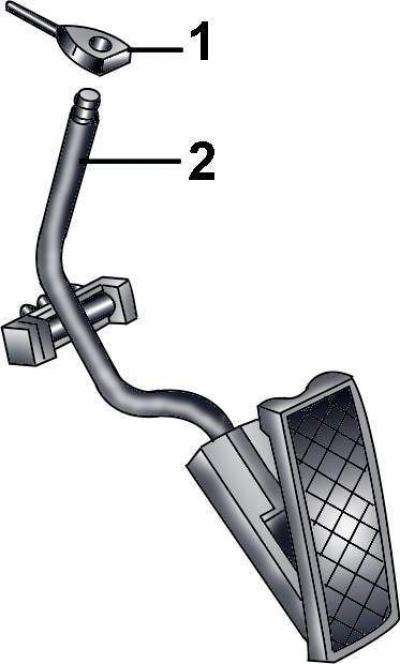
Fig. 4.1–15. Removing the accelerator cable (1) from the top of the accelerator pedal (2)
Disconnect the accelerator cable from the top of the accelerator pedal (Fig. 4.1–15)
Cars with automatic transmission
Disconnect the electrical connector from the downshift mechanism.
Remove the protective covers located on the left rear of the engine compartment.
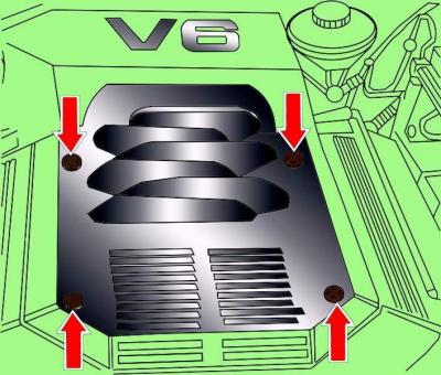
Fig. 4.1–16. Location of the six-cylinder engine casing mounting screws
Remove the four screws and remove the engine cover (Fig. 4.1–16; 4.1–17).
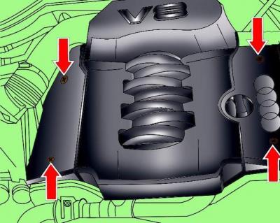
Fig. 4.1–17. Location of the eight-cylinder engine casing mounting screws
Cars with cruise control
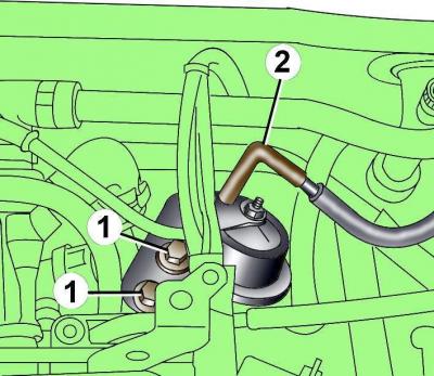
Fig. 4.1–18. Location of the vacuum hose (2) and bolts (1) for fastening the vacuum chamber of the cruise control system
Disconnect vacuum hose 2 from the cruise control system vacuum chamber (Fig. 4.1–18).
Remove the two bolts and remove the cruise control vacuum chamber from the bracket.
Cars with six-cylinder engines
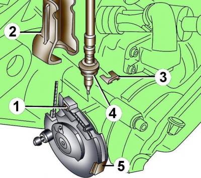
Fig. 4.1–19. Fastening the accelerator cable to the throttle lever of vehicles with six-cylinder engines: 1 – accelerator cable end; 2 – bracket; 3 – spring clamp; 4 – rubber bushing of the accelerator cable sheath; 5 – spring retainer
Using an 8 mm open-end wrench, disconnect the end of the accelerator cable 1 from the throttle actuator lever (Fig. 4.1–19).
Remove spring clip 3 securing the accelerator cable housing to bracket 2 and remove the cable from bracket 2.
Using a screwdriver blade as a lever, remove spring clip 5.
Pull the accelerator cable out engine compartment.
Cars with eight-cylinder engines
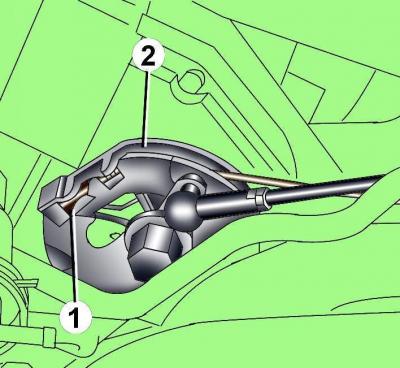
Fig. 4.1–20. Fastening the accelerator cable end (1) to the throttle actuator lever (2)
Disconnect the accelerator cable end from the throttle actuator lever (Fig. 4.1–20).
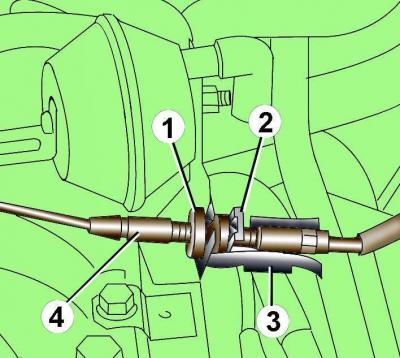
Fig. 4.1–21. Fastening the accelerator cable on cars with six-cylinder engines: 1 – rubber bushing; 2 – spring clamp; 3 – bracket; 4 – accelerator cable sheath
Remove spring clamp 2 (Fig. 4.1–21) and rubber bushing 1 with accelerator cable casing 4 from bracket 3.
Pull the accelerator cable out engine compartment.
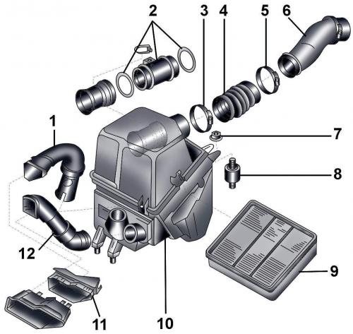
Fig. 4.1–22. Air filter: 1 – air duct; 2 – air flow meter G70; 3 – clamp; 4 – air intake duct; 5 – clamp; 6 – suction air duct; 7 – nut; 8 – rubber cushion; 9 – air filter element; 10 – air filter housing; 11, 12 – air duct
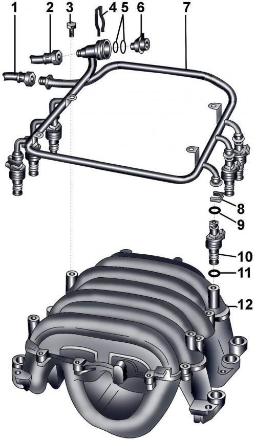
Fig. 4.1–23. Fuel line with injectors: 1 – fuel supply pipe from the fuel filter; 2 – fuel return pipe; 3 – bolt, 10 Nm; 4 – spring connector; 5 – sealing rings; 6 – fuel pressure regulator; 7 – fuel line; 8 – spring connector; 9 – sealing ring; 10 – nozzle; 11 – sealing ring; 12 – intake manifold
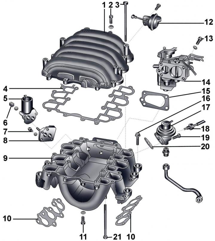
Fig. 4.1–24. Throttle body and intake manifold switching system: 1 – upper part of the intake manifold; 2 – bolt, 10 Nm; 3 – bolt, 20 Nm; 4 – gasket; 5 – idle speed stabilization valve N71; 6 – bolt, 10 Nm; 7 – bolt, 6 Nm; 8 – flange; 9 – intake manifold base; 10 – gasket; 11 – bolt, 10 Nm; 12 – vacuum chamber of the intake manifold switching valve; 13 – bolt, 20 Nm; 14 – throttle assembly; 15 – gasket; 16 – bolt, 20 Nm; 17 – mechanical valve of the exhaust gas recirculation system (EGR); 18 – EGR temperature sensor G98; 19 – bolt, 10 Nm; 20 – gasket; 21 – bolt, 10 Nm
Installation
Installation is carried out in the reverse order of removal.
Do not allow the accelerator cable to become kinked.
Adjust the accelerator cable.
Adjusting the accelerator cable
To adjust the position of the accelerator cable, the assistance of a second mechanic is required.
Remove the spring clip and rubber bushing with the accelerator cable housing from the bracket.
Press the accelerator pedal all the way down and adjust the accelerator cable position so that the throttle valve is fully open. The accelerator cable position is adjusted by moving the rubber bushing along the cable sheath. In this position, insert the rubber bushing of the sheath and secure it with the spring clip.
Note: New O-rings and gaskets must be used during installation.
(This article was previously published on the resource AudiManual.ru)