
If the engine is not running normally, first check the condition of the electrical wiring and connectors. Check the condition of the air filter element, as well as the condition and interelectrode gap of the spark plugs. Check the condition of the crankcase ventilation hoses and the adjustment of the accelerator cable. If the engine still continues to run unsteadily, check the compression in the engine cylinders.
Check the operation of the fuel injector and clean it if necessary.
If the engine still runs rough, check the ignition system components.
If the fault is not fixed, check the integrity of the fuses and the condition of the electrical connectors and wiring. There should be no melted contacts, moisture, dirt, corrosion or other damage on the electrical connectors.
After performing an independent check, contact a specialized station for diagnostics of the fuel injection system using special equipment.
The arrangement of the ignition and fuel injection system elements of a six-cylinder engine is shown in Figure 4.1–1, and of an eight-cylinder engine – in Figure 4.1–2.
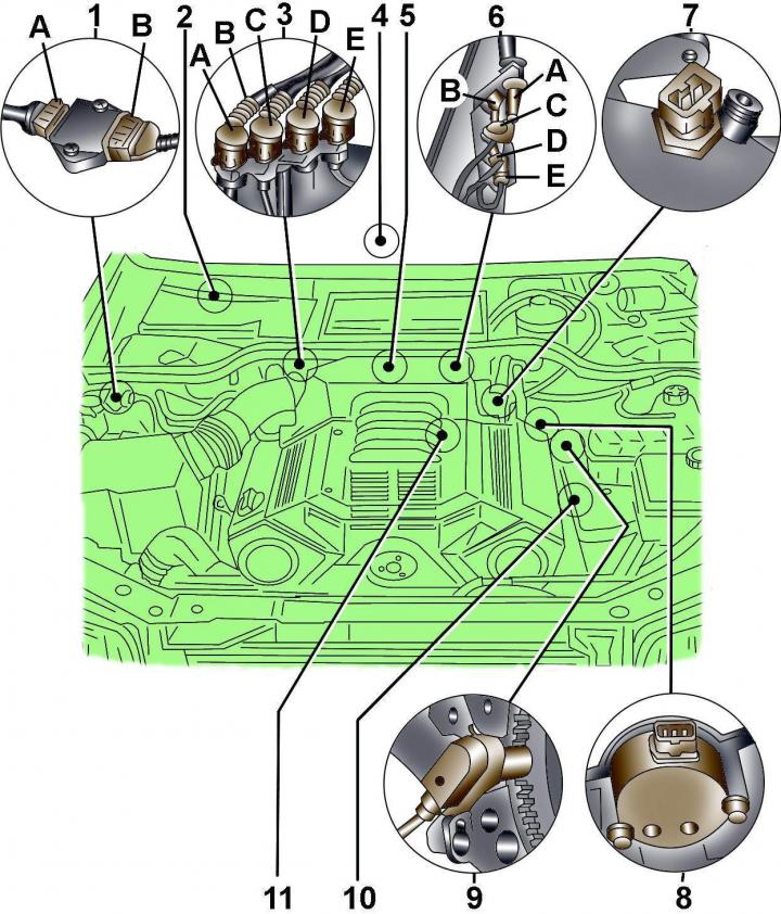
Fig. 4.1–1. Location of ignition and fuel injection system components in the engine compartment of vehicles with six-cylinder engines: 1 – switch N122; A - 3-pin dark brown connector for primary circuits of ignition coils; B – 4-pin brown connector from the control unit; 2 – Engine control unit J192; 3 – electrical connectors: A – black, 2-pin from the lambda sensor heater; B – 1-pin from lambda sensor; C – 3-pin brown, from the switch; D – 2-pin blue, from the knock sensor; E – 3-pin white, for power supply of ignition coils; 4 – diagnostic connector; 5 – throttle valve potentiometer with switch G69; 6 – electrical connectors: A – 2-pin black, for lambda sensor heater; B – 1-pin, from lambda sensor; C – 2-pin blue, from the knock sensor; D – 3-pin gray, from the speed sensor; E – 3-pin black, from the ignition timing sensor; 7 – Coolant temperature sensor G62; 8 – Hall sensor G40; 9 – speed sensor G28; 10 – ignition timing sensor G4; 11 – Knock sensor G66; 12 – ignition coils; 13 – injectors; 14-connection wire with "mass"; 15 – Air flow meter G70; 16 – electromagnetic valve 1st adsorber N80; 17 – Knock sensor G61; 18 – fuel pressure regulator; 19 – Lambda sensor G39; 20 – Fuel pump relay J17; 21 – idle speed stabilization valve N71; 22 – "ground" connection wire; 23 – Intake manifold changeover valve N156; 24 – Lambda sensor G108
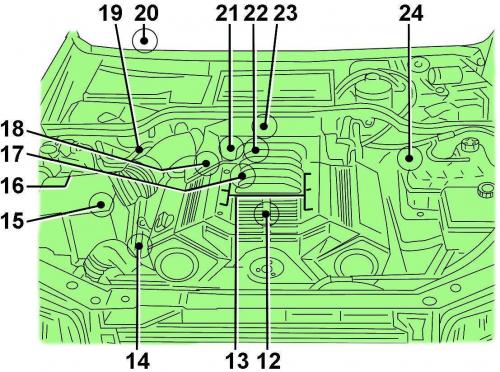
Fig. 4.1–1. Location of ignition and fuel injection system components in the engine compartment of vehicles with six-cylinder engines: 1 – switch N122; A - 3-pin dark brown connector for primary circuits of ignition coils; B – 4-pin brown connector from the control unit; 2 – Engine control unit J192; 3 – electrical connectors: A – black, 2-pin from the lambda sensor heater; B – 1-pin from lambda sensor; C – 3-pin brown, from the switch; D – 2-pin blue, from the knock sensor; E – 3-pin white, for power supply of ignition coils; 4 – diagnostic connector; 5 – throttle valve potentiometer with switch G69; 6 – electrical connectors: A – 2-pin black, for lambda sensor heater; B – 1-pin, from lambda sensor; C – 2-pin blue, from the knock sensor; D – 3-pin gray, from the speed sensor; E – 3-pin black, from the ignition timing sensor; 7 – Coolant temperature sensor G62; 8 – Hall sensor G40; 9 – speed sensor G28; 10 – ignition timing sensor G4; 11 – Knock sensor G66; 12 – ignition coils; 13 – injectors; 14-connection wire with "mass"; 15 – Air flow meter G70; 16 – electromagnetic valve 1st adsorber N80; 17 – Knock sensor G61; 18 – fuel pressure regulator; 19 – Lambda sensor G39; 20 – Fuel pump relay J17; 21 – idle speed stabilization valve N71; 22 – "ground" connection wire; 23 – Intake manifold changeover valve N156; 24 – Lambda sensor G108
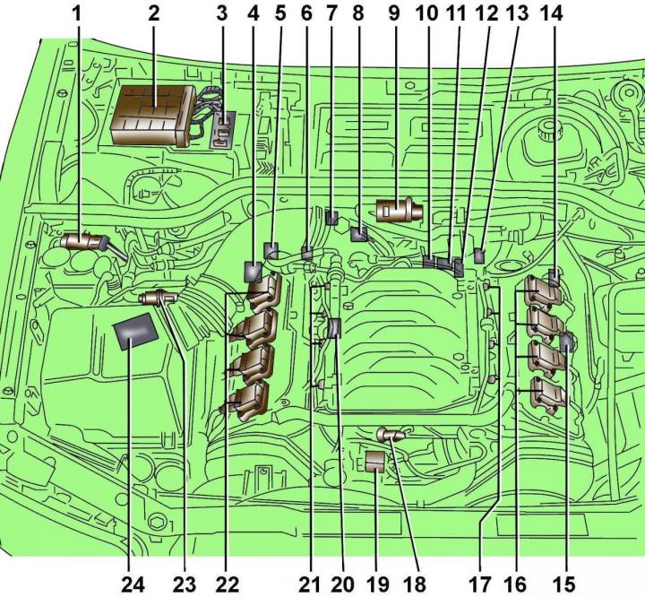
Fig. 4.1–2. Location of ignition and fuel injection system components in the engine compartment of vehicles with eight-cylinder engines: 1 – ignition coil switch N122, N192; 2 – Engine control unit J220; 3 – fastening element for relays and fuses; motronic Power Supply Relay J271; immobilizer Relay J341; 4 – electrical connectors of lambda sensor G39 and lambda sensor heater Z19; 5 – lambda sensor G39 with heater Z19; 6 – coolant temperature sensor G62; 7 – engine air temperature sensor G42, 8 – throttle valve potentiometer G69, combined with idle speed switch F60; 9 – idle speed stabilization valve N71; 10 – Engine speed sensor G28; 11 – electrical connector of lambda sensor G108 and heater Z28; 12 – Electrical connector of engine speed sensor G28; 13 – Lambda sensor G108 with heater Z28; 14 – Hall sensor G40; 15 – Knock sensor G66; 16 – ignition coils of cylinders 5–8, respectively N164, N189, N190, N191; 17 – fuel injectors for cylinders 5–8 respectively N83, N84, N85, N86; 18 – air control valve for injectors N₂12 (installed only on vehicles with engine code AKG/ AKJ/ AKH (MVEG III) and OBDII; 19 – Intake manifold changeover valve N156; 20 – Knock sensor G61; 21 – injectors of cylinders 1–4, respectively N30, N31, N32, N33; 22 – ignition coils of cylinders 1–4, respectively N, N128, N158, N163; 23 – electromagnetic valve 1st adsorber N80; 24 – G70 air flow meter in the upper section of the air filter housing