
Table of contents: Installation of a control pressure… ↓ Checking the performance of the fuel… ↓ Checking the control pressure ↓ Checking the fuel pressure in the… ↓ Checking residual pressure ↓ Checking the injection nozzles ↓
Installation of a control pressure gauge
To check the pressure, use a VW 1318 pressure gauge with a nipple and a tap that measures both the flow pressure and the inlet pressure.
Connect the pressure gauge hoses between the dispenser-distributor and the control pressure supply pipeline coming from the control pressure regulator.
Remove air locks from the pressure gauge hoses. To do this, start the engine, set the pressure gauge valve to the position for monitoring the pressure gauge and lower the pressure gauge so that it hangs freely on the hoses.
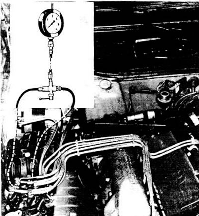
Wiring diagram for a pressure gauge to check fuel pressure in the injection system
Checking the performance of the fuel pump
Increase the fuel pressure in the injection system.
Disconnect the fuel drain hose from the fuel pump into the tank and lower the hose into the measuring cup.
Remove the fuel pump relay from the mounting block socket.
Connect the "+" terminal of the battery to the power terminal of the fuel pump using a shunt with a switch.
Install on;0 s the switch on the shunt is in the "on" position, thereby activating the fuel electric pump.
Measure the amount of fuel that flows out into the measuring cup, which should be 900 cm³.
If the amount of fuel in the measuring cup is not within the norm, check the technical condition of the fuel filter and fuel pump.
Checking the control pressure
Connect the fuel pressure test gauge as shown above.
Start a cold engine.
Measure the control pressure, which for the "WC", "KR", "KU" engines should be within 1.5±0.15 kg/cm², for the "RT" engine - 1.55-1.75 kg/cm².
Warm up the engine to operating temperature.
Measure the control pressure, which for the engines "WC", "KR", "KU" should be within 3.4-3.8 kg/cm², for the engine "RT" - 4.1-4.3 kg/cm².
Determine the fault from the table if the data obtained during the test do not correspond to the nominal values.
Checking the pressure in the fuel injection system
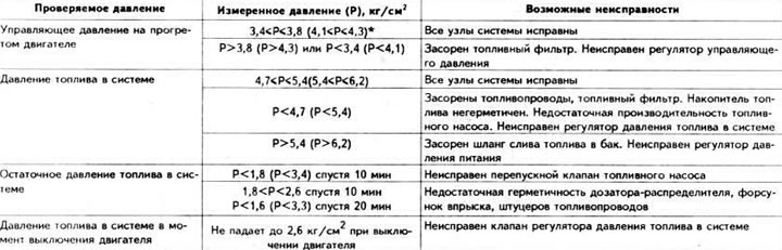
* The values in brackets are for the "RT" engine.
Checking the fuel pressure in the system
Check the fuel pump performance as described above.
Install a fuel pressure gauge.
Set the pressure gauge valve to the "closed" position to measure the fuel pressure at the inlet.
Start the engine.
Measure the fuel pressure in the system, which for the "WC", "KR", "KU" engines should be in the range of 4.7-5.4 kg/cm², for the "RT" engine - 5.4-6.2 kg/cm².
Determine the fault from the table if the data obtained during the test do not correspond to the nominal values.
Checking residual pressure
Warm up the engine to operating temperature.
Install a fuel pressure gauge.
Leave the engine to idle.
Set the pressure gauge valve to the "open" position to measure the flow pressure.
Measure the control pressure using the pressure gauge.
Turn off the ignition.
Determine the residual fuel pressure in the system 10 and 20 minutes after stopping the engine and compare with the nominal values (see subsection "Detailed technical specifications").
Determine the fault using the table if the data obtained during the test does not correspond to the nominal values.
Checking the fuel pressure when the engine is turned off
Warm up the engine to operating temperature.
Install a fuel pressure gauge
Set the pressure gauge valve to the "closed" position to measure the inlet pressure.
Measure the fuel pressure in the system and compare it with the nominal value (see "Detailed technical specifications"),
Turn off the ignition.
Measure the fuel pressure in the system at the moment the ignition is turned off, which should drop to 2.6 kg/cm².
Checking the injection nozzles
Disconnect the wire from the negative terminal of the battery.
Unscrew the nozzles from their sockets and place them in measuring cups.
Remove the fuel pump relay from the mounting block socket.
Connect the "+" terminal of the battery to the power terminal of the fuel pump using a shunt with a switch.
Connect the negative cable to the battery.
Set the switch on the shunt to the "on" position, thereby activating the fuel pump. In this case, not a single drop of fuel should appear from the injector nozzles for at least 2 minutes.
Remove the air line from the air flow meter to the throttle body.
Lift the air flow meter pressure disc.
Keep the pressure disc in the raised position until the fuel level in one of the measuring cups reaches a certain level.
Compare how much the fuel level in the measuring cups differs. The permissible difference in the amount of fuel that has flowed into the measuring cups is 0.6 ml.
If there is any deviation from the norm, replace the faulty injectors.
This article was copied from the website: audimanual.ru