
Repair Chevrolet Repair Toyota Repair Honda Repair AvtoVAZ Repair Mercedes-Benz Repair BMW Repair Opel
Home  |  Contacts  |  Sitemap  |    
English Русский
Български
Беларускі
Український
Српски
Hrvatski
Română
Polski
Slovenský
Magyar
AudiManual.ru


  • AUDI 80
  • AUDI 100
  • AUDI A3
  • AUDI A4
  • AUDI A6
  • AUDI A8
  • AUDI Q
  • OTHER
  • ARTICLES
C4 (1990-1994) C4 (1990-1994, petrol) C3 (1982-1990) C3 (1982-1990, petrol) C3 (1982-1990, diesel)

Checking and adjusting the Keihin carburetor (Audi 100 C3)

  • Home
  • Audi 100
  • C3 (1982-1990, petrol)
  • 5 cylinder engine
  • Supply system
  • Checking and adjusting the Keihin carburetor
            0
Table of contents: Checking the fuel level in the float… ↓ Adjusting the opening of the… ↓ Adjusting the throttle valve… ↓ Adjusting the starting clearance of… ↓ Adjusting the performance of the… ↓ Adjusting the idle speed of a warm… ↓

Checking the fuel level in the float chamber


The position of the float in the float chamber is not adjustable. If a malfunction is detected, check the float for leaks, check the operation of the needle valve, replace faulty parts.

Adjusting the opening of the throttle valve of the 1st chamber when the cold engine is idling


To adjust without removing the carburetor from the engine, warm up the engine to operating temperature.

Remove the air filter.

Disconnect the vacuum supply hose from the 1st chamber throttle actuator.

Attach a reference tachometer.

Start a cold engine and let it idle.

Check the crankshaft speed using the tachometer, which should be 3500 rpm.

If necessary, adjust the idle speed of the cold engine crankshaft by moving the fork-type lever of the 1st chamber throttle valve drive.

Remove the carburetor and check the opening of the throttle valve of the 1st chamber, which on cars with a manual transmission should be within 1.3-0.1 mm, on cars with an automatic transmission - 1.5±0.1 mm.

If there is a deviation from the norm, achieve the proper opening of the throttle valve of the 1st chamber by acting on the fork lever of its drive.
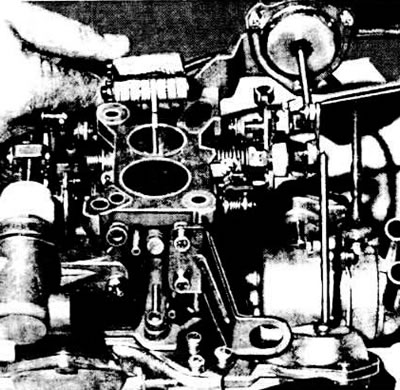
Adjusting the opening of the throttle valve of the 1st chamber when the cold engine is idling

Adjusting the opening of the throttle valve of the 1st chamber when the cold engine is idling


Adjusting the throttle valve starting clearance


Remove the carburetor and disconnect the pneumatic drive rod from the throttle valve of the 1st chamber.

Insert a 9.5mm diameter drill bit between the carburetor body and the automatic starting device actuated throttle control lever.

If necessary, achieve the proper clearance by changing the length of the automatic starting device drive rod.

Measure the throttle valve starting clearance using a set of feeler gauges, which should be 0.6±0.07 mm on vehicles with a manual transmission and 0.7±0.07 mm on vehicles with an automatic transmission.

If there is a deviation from the norm, set the required starting clearance by changing the position of the throttle control lever thrust roller.
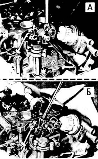
Adjusting the starting clearance of the throttle valve of a cold engine: A - adjustment of the…

Adjusting the starting clearance of the throttle valve of a cold engine: A - adjustment of the output of the drive rod of the automatic starting device; B - adjustment of the position of the thrust roller


Adjusting the starting clearance of the air damper


Remove the air filter.

Remove the automatic starting device cover.

Set the air damper control lever to the stop position by turning it counterclockwise and lock it in this position.


Set the air damper pneumatic actuator rod to the stop position.

Using a set of feeler gauges, measure the starting clearance of the air damper, which should be 5.6±0.15 mm.

If necessary, adjust the air damper starting clearance by bending the stop lever.

Adjusting the opening of the throttle valve of the 2nd chamber

Remove the carburetor.

Loosen the 2nd chamber throttle valve limit screw until it is clear of the bracket. Tighten the limit screw until it touches the bracket, then tighten it another 1/2 turn.

Lock the 2nd chamber throttle valve limit screw with a drop of paint.

After installing the carburetor, adjust the engine idle speed.
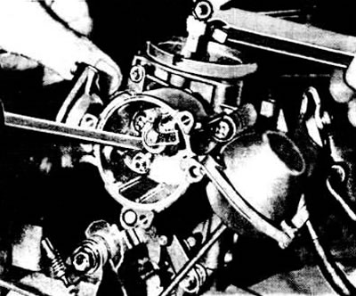
Adjusting the starting clearance of the air damper

Adjusting the starting clearance of the air damper


Adjusting the performance of the accelerator pump


Remove the carburetor and place a measuring cup with a funnel underneath it.

Move the automatic starting device control lever towards the opening direction.

Move the throttle control lever of the 1st chamber away from the rod and pneumatic drive.

Install a 12 mm diameter rod between the carburetor body and the 1st chamber throttle control lever, driven by an automatic starting device.


Smoothly open and close the throttle valve of the 1st chamber completely, thereby activating the accelerator pump.

Measure the amount of fuel that has flowed into the measuring cup and compare it with the standard (see subsection "Detailed technical specifications").

If there is a deviation from the norm, adjust the required performance of the accelerator pump by changing the stroke of the accelerator pump drive lever, slightly bending the stop lever.
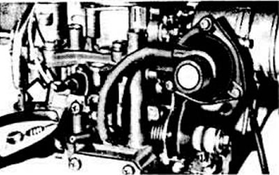
Adjusting the accelerator pump

Adjusting the accelerator pump


Adjusting the idle speed of a warm engine


Before adjusting the idle speed, check that the ignition timing is set correctly and turn off all electrical consumers.

Warm up the engine to operating temperature.

Attach a reference tachometer.

Adjust the engine idle speed by turning the stop screw of the 1st chamber throttle control lever, which rests on the 1st chamber throttle pneumatic drive lever.

Connect the gas analyzer according to the operating instructions.

Remove the air cleaner cover and disconnect the crankcase ventilation hose.

Check and, if necessary, adjust the CO content using the idle mixture quality (composition) screw.
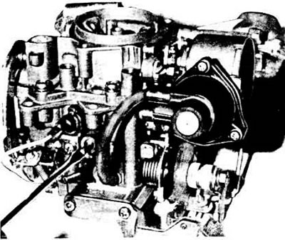


Adjustment of carbon monoxide (CO) content in exhaust gases

Adjustment of carbon monoxide (CO) content in exhaust gases


Check and, if necessary, readjust the engine idle speed.
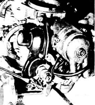
Adjusting engine idle speed

Adjusting engine idle speed
The article was checked by auto expert Maxim Rybakov
This article is available at russian, bulgarian, belarusian, ukrainian, serbian, croatian, romanian, polish, slovak, hungarian

Share information:
Previous articles
Audi 100 C3: Supply system
Next articles

Keihin carburetor — operating principle
Main parts of the Keihin carburetor
Engine power system model «WH»
Power supply system — technical characteristics
Fuel injection system «K-Jetronic» of engines «WC», «KU» and «RT»
Checking and adjusting the fuel injection system «K-Jetronic»
Removal and installation the metering unit with air flow meter
Removal and installation of injection nozzles (K-Jetronic)


Similar articles on other Audi car models:
Checking and adjusting the Keihin 26-30 DC carburetor Audi 80 B2 (1979-1986)
Checking and adjusting idle speed / ignition timing / CO… Audi A3 Type 8L (1996-2003)
Checking the brake system. Adjusting the parking brake Audi A4 B6 (2000-2006)
Checking and adjusting idle speed, ignition timing and CO content Audi A6 C5 (1997-2004)
Checking the exhaust system Audi A8 D2 (1994-2002)
Replacing the coolant, checking and adjusting its level,… Audi Q7 Typ 4L (2005-2015, diesel)
Headlights — checking adjustment, adjusting if necessary Audi A2 (1999-2005)
Link to this page in different formats


Visitor comments

No comments yet


How much will 46 + 39 =


100(C4, 1990-1994) 
  • General information
  • User manual
  • Power unit
  • Engine repair
  • Ignition system
  • Fuel system (gasoline)
  • Fuel system (diesel)
  • Lubrication system
  • Cooling system
  • Exhaust system
  • Transmission
  • Clutch
  • Car gearbox
  • Drive shafts
  • Chassis
  • Car suspension
  • Steering
  • Wheels and tires
  • Brake system
  • Body
  • Ventilation and heating
  • Body repair
  • Electrical equipment
  • Power devices
  • Lighting and appliances
  • Electrical circuits
 
100(C4, 1990-1994, petrol) 
  • General information
  • Operation and maintenance
  • Power unit
  • Engine repair
  • Exhaust system
  • Cooling system
  • Supply system
  • Air filter
  • Mono-Motronic injection system
  • Digifant injection system
  • KE-III-Jetronic and KE-Motronic
  • MPI and MPFI injection system
  • Transmission
  • Clutch
  • Car gearbox
  • Chassis
  • Suspension and steering
  • Brake system
  • Wheels and tires
  • Body
  • Exterior
  • Interior
  • Electrical equipment
  • Fuses and relays
  • Power devices
  • Ignition system
  • Lighting and signaling
  • Equipment and devices
  • Electrical circuits
 
100(C3, 1982-1990) 
  • General information
  • User manual
  • Maintenance
  • Specifications
  • Power unit
  • Engines 4-cylinder
  • Engines 5-cylinder
  • Diesel engine
  • Cooling system
  • Power system (carburetor)
  • Power system (injector)
  • Fuel system (diesel)
  • Transistor ignition system
  • Electronic ignition system
  • Transmission
  • Clutch
  • 4 speed gearbox 014
  • 5 speed gearbox 013 and 093
  • 5 speed gearbox 016 and 012
  • Shift mechanism KP 016
  • Automatic transmission
  • Front wheel drive
  • Chassis
  • Front suspension
  • Rear suspension
  • Steering
  • Brake system
  • Body
  • Body elements
  • Electrical equipment
  • Lighting and appliances
  • Power devices
  • Electrical circuits
 
100(C3, 1982-1990, petrol) 
  • General information
  • Maintenance and operation
  • 4 cylinder engine
  • Engine repair
  • Cooling and lubrication system
  • Supply system
  • Ignition system
  • 5 cylinder engine
  • Engine repair
  • Cooling and lubrication system
  • Supply system
  • Ignition system
  • Transmission
  • Clutch and drive shafts
  • 4 speed gearbox 014
  • 5 speed gearbox 013 and 093
  • 5 speed gearbox 016 and 012
  • Automatic gearbox
  • Chassis
  • Steering
  • Front suspension
  • Rear suspension
  • Brake system
  • Body
  • Body elements
  • Doors, locks and windows
  • Body repair
  • Electrical equipment
  • Equipment and devices
  • Power devices
  • Electrical circuits
 
100(C3, 1982-1990, diesel) 
  • General information
  • User manual
  • Maintenance
  • Troubleshooting
  • Power unit
  • Engine in a car
  • Engine removed
  • Cooling system
  • Fuel system
  • Exhaust system
  • Starting and charging
  • Preheating
  • Transmission
  • Clutch
  • Mechanical gearbox
  • Automatic gearbox
  • Drive shafts
  • Chassis
  • Brake system
  • Suspension
  • Steering
  • Body
  • Exterior
  • Interior
  • Electrical equipment
  • Equipment and devices
  • Electrical circuits
 
AudiManual.ru © 2017-2026 · Mobile version · Feedback · Sitemap: EN BG BY UA RS HR RO PL SK HU · Site search · News and articles
80 B2 · 80 B3 petrol · 80 B3 · 80 B4 · 100 C3 diesel · 100 C3 petrol · 100 C3 · 100 C4 petrol · 100 C4 · A3 Type 8L · A4 B5 petrol · A4 B5 · A4 B6 petrol · A4 B6 · A4 B7 · A4 B8 · A6 C4 · A6 C5 · A6 C5 Allroad · A8 D2 · Q5 Type 8R · Q7 Typ 4L · Audi A2 ·
This site uses cookies 🍪. Click the button to accept this fact.