
Table of contents: Operating principle of the fuel… ↓ Operation under load and idle… ↓ Cold engine start ↓ Starting a hot engine ↓
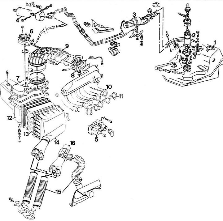
Fuel system of engines with fuel injection system "K-Jetronic": 1 - fuel tank; 2 - fuel pump; 3 - fuel storage tank; 4 - fuel filter; 5 - control pressure regulator; 6 - fuel dispenser; 7 - air flow meter; 8 - throttle body; 9 - connecting air duct; 10 - inlet manifold; 11 - intake manifold gasket; 12 - Air filter and air flow meter bracket; 13 - air filter; 14 - Air filter housing; 15 - air supply hoses; 16 - thermostat
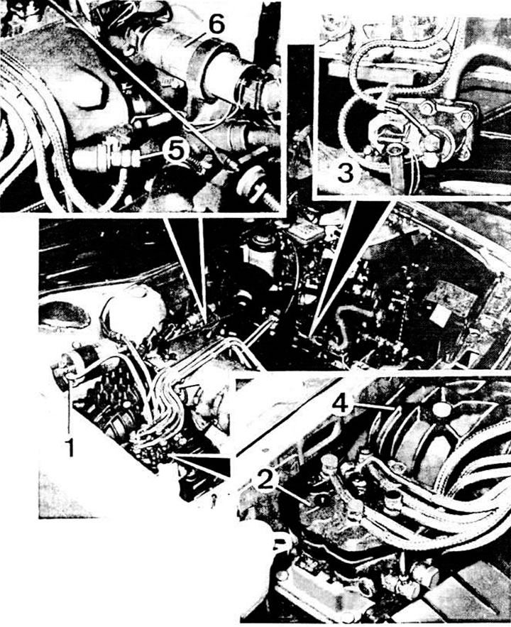
Location of the K-Jetronic fuel injection system: 1 - fuel filter; 2 - fuel dispenser; 3 - control pressure regulator; 4 - air flow meter; 5 - starting nozzle; 6 - additional air supply valve
Operating principle of the fuel injection system "K-Jetronic"
Fuel under pressure is continuously supplied to the injection nozzles located directly in front of the intake valves. The amount of fuel injected by the nozzles is dosed by the pressure of the incoming fuel depending on the engine load (vacuum in the intake manifold) and from the temperature of the coolant. The amount of injected fuel is adjusted by the metering distributor, which operates under the influence of the air flow meter and the control pressure regulator. During engine warm-up, the latter regulates the control pressure depending on the vacuum in the intake manifold and the temperature of the coolant.
The amount of air supplied is continuously measured by the air flow meter, and the amount of fuel injected is strictly proportional to the amount of air supplied (with the exception of a number of engine operating modes, such as cold engine starting, full load mode, etc.) and is regulated by a fuel dispenser-distributor.
Operation under load and idle conditions
Fuel electric pump 1 (see diagram) takes fuel from the fuel tank and pumps it 2 under pressure of about 5 kg/cm² into the metering distributor 2 through the fuel filter 4 and the fuel accumulator 3.
Fuel under supply pressure fills the lower chambers 5 of the metering distributor and presses the diaphragms of the differential pressure valves 6 to the tubes 7 supplying fuel to the injectors. Fuel under pressure penetrates into the upper chambers of the metering distributor through the slots in the walls of the distribution plunger 8. The amount of fuel entering the upper chambers of the metering distributor changes depending on the vertical movement of the distribution plunger.
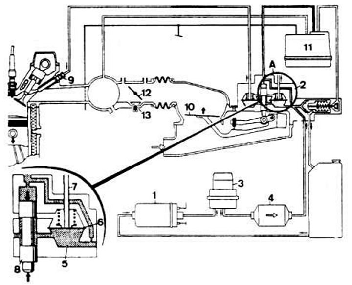
Scheme of operation of the K-Jetronic injection system in load and idle modes: 1 - fuel pump; 2 - fuel dispenser; 3 - fuel storage tank; 4 - fuel filter; 5 - dosing chamber; 6 - differential pressure diaphragm valve; 7 - fuel supply pipe to the injection nozzle; 8 - distribution plunger; 9 - injection nozzle; 10 - air flow meter pressure disk; 11 - control pressure regulator; 12 - throttle valve; 13 - idle speed adjusting screw
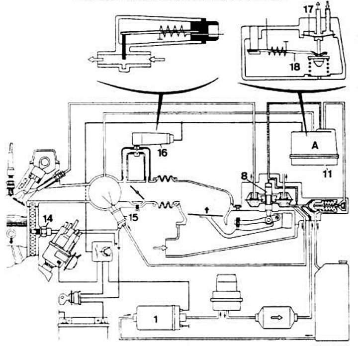
Scheme of operation of the K-Jetronic injection system when starting a cold engine: 1 - fuel pump; 8 - distribution plunger; 11 - control pressure regulator; 14 coolant temperature sensor; 15 starting nozzle; 16 - additional air supply valve; 17 - diaphragm valve for regulating control pressure; 18 - bimetallic spring for controlling the control pressure adjustment valve
When the total fuel pressure in the upper chambers and the spring pressure exceed the fuel supply pressure in the lower chambers, the diaphragms of the valves 6 are lowered, opening access of fuel through the tube to the injection nozzle 9. As soon as the pressure in the upper chambers of the metering distributor decreases, the diaphragms of the valves 6 return to their original position. Due to the uniform periodicity of opening and closing of the fuel supply channels to the nozzles, a constant fuel pressure is established. The displacement of the pressure disk 10 of the air flow meter is transmitted through the lever to the distribution plunger, the return of which to its original position occurs due to the counteracting fuel pressure in the upper part of the metering distributor. The counteracting pressure is created due to the supply pressure and is regulated by the control pressure regulator 11.
The additional air supply valve 16 is installed in the air channel, made parallel to the throttle valve 12. It ensures a minimum vacuum in the air flow meter when the engine is idling. The degree of opening of the additional air supply valve is regulated by the adjusting screw.
Cold engine start
Fuel electric pump 1 instantly creates working fuel pressure in the system. At the moment of starting a cold engine and for a certain time, starting nozzle 15 injects an additional amount of fuel into the intake manifold.
The duration of the starting injector operation is determined by the thermal time relay depending on the coolant temperature. Valve 16 supplies additional air to the engine to increase the crankshaft speed of a cold engine at idle. Additional enrichment of the fuel-air mixture during starting and warming up of a cold engine is achieved due to a freer lift of the distributor plunger 8 due to the fact that the control pressure regulator 11 reduces the counteracting return pressure.
Until the engine is warmed up, the bimetallic spring 18 compresses the spring of the diaphragm valve 17, opening the fuel drain channel, which leads to a decrease in the counteracting pressure on the distribution plunger.
Starting a hot engine
To completely eliminate fuel evaporation after the engine has stopped, the pressure in the injection system is maintained for some time by a fuel accumulator, which temporarily interrupts the flow of fuel into the tank.
The text is based on materials from the website Audimanual.ru