



Table of contents: Fuel tank ↓ Engine power system model "WH" ↓ Fuel injection system "K-Jetronic" ↓ Fuel injection system "KE-Jetronic" ↓
The engine of the "WH" model is powered by a Keihin carburetor, engines of the models "KP", "WC", "KU" and "RT" mechanical continuous fuel injection system "K-Jetronic", and "NF" models - mechanical continuous fuel injection system with electronic pressure regulation "KE-Jetronic".
Fuel tank
The fuel tank is stamped from sheet steel and is located in front of the rear axle.
Fuel tank capacity, l: 80.
Engine power system model "WH"
Air filter
Air filter with replaceable dry filter element. Brand and type: Mann C 2852/2.
Fuel pump
The fuel pump is driven by the camshaft eccentric.
Fuel supply pressure, kg/cm²: 0.35-0.40.
Keihin carburetor
Keihin carburetor, emulsion type, two-chamber, with sequential opening of throttle valves.
The carburetor has two main metering systems of the 1st and 2nd chambers, an idle system of the 1st chamber with a transition system, a transition system of the 2nd chamber, and a blocking of the second chamber; power mode economizer, diaphragm accelerator pump, electromagnetic shut-off valve, automatic starting and heating device of mixed type, which uses a bimetallic spring with electric heating and circulation of heated liquid from the engine cooling system and uses a pneumatic drive of the air damper and a device for electric heating of the intake manifold. The carburetor has a pneumatic drive of the throttle valve of the 1st chamber, controlling its movements in idle and forced idle modes, as well as a pneumatic drive of the throttle valve of the 2nd chamber, controlled by a thermal pneumatic valve and allowing the throttle valve of the 2nd chamber to move only on a hot engine.
Thermo-pneumatic valve for controlling the pneumatic drive of the 2nd chamber throttle valve.
This valve is installed on the left side of the cylinder head. Valve closing temperature,°C: < 48.
Valve opening temperature,°C: > 58.
Keihin carburetor calibration data
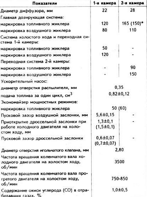
* The values in brackets are for vehicles with automatic transmission.
Fuel injection system "K-Jetronic"
On the engines of models "KP", "WC". "KU" and "RT" uses the mechanical system of continuous fuel injection "K-Jetronic" from Bosch. Engines of the models "KU", "KP", "RT" have a forced idle system.
The principle of operation of the fuel injection system
The fuel pump takes fuel from the fuel tank and delivers it to the accumulator. Then the fuel is supplied under pressure through the filter to the fuel dispenser-distributor.
The pressure disk of the air flow meter, which is fixed on the movable lever and installed between the air filter and the throttle valve, deflects depending on the vacuum of the air in the engine. The displacement of the pressure disk of the air flow meter is transmitted to the distribution plunger of the fuel metering unit, thereby determining the amount of fuel supplied. The fuel quantity distributor, depending on the position of the pressure disk of the air flow meter, supplies the required amount of fuel to the engine cylinders through the injectors, ensuring the optimal composition of the fuel-air mixture. The fuel metering unit and the air flow meter form a mixture regulator.
The control pressure regulator reduces the pressure on the distribution plunger during engine warm-up. Reducing the control pressure with the same air flow leads to an increase in fuel supply and, consequently, to enrichment of the combustible mixture.
The additional air supply valve, installed in the air channel parallel to the throttle valve, supplies an additional amount of air to the engine during cold starting and warming up of the engine, which leads to an increase in the engine crankshaft speed at idle.
To facilitate starting a cold engine, an electromagnetic starting injector is provided, the opening duration of which changes depending on the temperature of the coolant by a thermal time relay.
Air filter
Air filter with replaceable dry filter element.
Brand and type: Mann C 22117 or Purflux A 515.
Fuel electric pump
The fuel electric pump is placed in the fuel tank in a submerged position.
Brand and catalog number: Bosch 0 580 254 003 or 0 580 254 004.
Productivity at terminal voltage of 12 V, l/min: 2.0.
Current consumption at terminal voltage of 12 V, no more than, A. 8.5.
Fuel storage tank
The fuel storage tank is installed under the body bottom next to the fuel tank on the right.
Brand and catalog number: Bosch 0 438 170 040 or 0 438 170 041.
Fuel filter
The fuel filter is located under the hood of the powertrain compartment.
Brand and catalog number: Bosch 0 450 905 091 or 0 450 905 092.
Damper
Brand and catalog number: Bosch 0 280 161 200; 0 280 161 201; 0 280 161 210 or 0 280 161 211.
Control pressure regulator
Brand and catalog number: Bosch 0 438 140 094; 0 438 140 095; 0 438 140 130 or 0 438 140 131.
Resistance of the heating winding of the bimetallic spring of the regulator. Ohm: 16-22.
Fuel dispenser
Brand and catalog number: Bosch 0 438 100 127.
Injection nozzles
Brand and catalog number: Bosch 0 437 502 023 or 0 437 502 024.
Volume of injected fuel, ml:
- at idle: 3.0 (2.5)*;
- at full load: 8.0.
Injection start pressure, kg/cm²: 3.0-4.1 (4.3-4.6).
Maximum permissible difference in injection start pressure between injection nozzles, kg/cm²: 0.6.
* The values in brackets are for the "RT" model engine.
Starting nozzle
Brand and catalog number: Bosch 0 280 170 400.
Air flow meter
Make and catalog number: Bosch 0 438 120 181 or 0 438 120 182 until July 1983.; 0 438 120 023 or 0 438 120 024 after July 1983.
Additional air supply valve
Brand and catalog number: Bosch 0 280 140 112.
Thermal cold start time relay
Brand and catalog number: Bosch 0 280 130 214 or 0 280 130 223.
Fuel shut-off valve (engines models "KU", "KP" and "RT")
Brand: VDO.
Operating voltage, V: ~12.
The valve opens at a crankshaft speed of more than 1200-2000 rpm when the throttle valve is closed on a warm engine.
Data for adjustment
Crankshaft speed at idle, rpm: 750-850 (on the "RT" engine, when the engine is idling, the control current of the regulating valve should be within 430±10 mA).
Carbon monoxide (CO) content in exhaust gases at idle speed, %: 1.0 (RT engine model: 1.0±0.2%).
Fuel pressure in the system, kg/cm²:
- model engines "WC", "KP", "KU": 4,7-5,2;
- engines model "RT": 5.4-6.2.
Control pressure (model engines "WC", "KP", "KU"), kg/cm²:
- with the vacuum hose of the control pressure regulator connected on a warm engine: 3.4-3.8;
- with the vacuum hose of the control pressure regulator disconnected (except for the "KP" engine): 2.75-3.05;
- with the vacuum hose of the control pressure regulator disconnected (engine "KP"): 2.75-3.05,
- on a cold engine at a temperature of 20°C 1.5±0.15.
Control pressure (engine model "RT"), kg/cm²:
- with the vacuum hose of the control pressure regulator disconnected on a warm engine: 2.65-2.95;
- with the vacuum hose of the control pressure regulator connected on a warm engine: 4.1-4.3;
- on a cold engine: 1.55-1.75.
Residual fuel pressure in the system, kg/cm²:
- 10 minutes after the engine stops:
- engines "WC", "KP", "KU": 1.8-2,6;
- engine "RT": > 3,4;
- 20 minutes after the engine stops:
- engines "WC", "KP", "KU": 1,6;
- engine "RT": 3.3.
Fuel injection system "KE-Jetronic"
The "NF" model engine uses a mechanical system of continuous fuel injection with electronic pressure regulation "KE-Jetronic". The system has a forced idle device, an oxygen concentration sensor and a three-component neutralizer of exhaust gases.
Fuel electric pump
Brand and catalog Ms Bosch 0 580 254 031 or C 580 254 032.
Fuel filter
The fuel filter is installed in the power unit compartment.
Brand and catalog M; Bosch 0 450 905 145 or C 450 905 146.
Fuel storage tank
Brand and catalog number Bosch 0 438 70 052 or 0 438 70 053.
Fuel dispenser
Brand and catalog number: Bosch 0 438 01 029.
Fuel pressure regulator
Brand and catalog number: Me- Bosch 0 438 61 016 or 0 438 61 017.
Idle speed control valve
Brand and catalog Bosch 0 280 140 512 or 0 280 140 513.
Electromagnetic injection nozzles
Brand and catalog Ns: Bosch 0 437 502 032 or 0 437 502 033.
Electronic control unit
The electronic control unit is installed in the car interior in front of the right front door, under the trim.
Brand and catalog number: Bosch 0 280 800 252 or 0 280 800 253.
Data for verification and adjustment
Fuel pressure in the system, kg/cm² 6.1-6.5.
Control pressure at nominal fuel pressure in the system, kg/cm²:
- with the control pressure regulator connector connected: 1.2-1.5;
- with the control pressure regulator connector disconnected: 0.3-0.5.
Residual fuel pressure in the system, not less than, kg/cm²:
- 10 minutes after engine stop: 3.5;
- 20 minutes after engine stop: 3.4.
Injector injection start pressure, kg/cm²: 4.3-4.6.
Difference in volume of fuel injected by injectors, ml:
- at idle speed with fuel injection volume of 20 ml/min:±3;
- at full load with a fuel injection volume of 80 ml/min: ±8.
Duration of fuel injection by the starting injector, s:
- at -20°C: 5-11;
- at 0°C: 2.0-2.5;
- at a temperature of 10-20°C: 0.
Supply current of the control pressure regulator, mA:
- when checking (when the engine is hot and idling): from -3 to +3;
- when adjusting (when the engine is hot and idling): 0±1.
Resistance of the control pressure regulator. Ohm: 17.5-21.5.
Engine crankshaft speed at idle, rpm: 650-790.
Carbon monoxide (CO) content in exhaust gases at idle, %: 0.1-1.1.
(The original version is on the portal: audimanual)