
The location of the power supply system components is shown in Figures 1.1a-u.
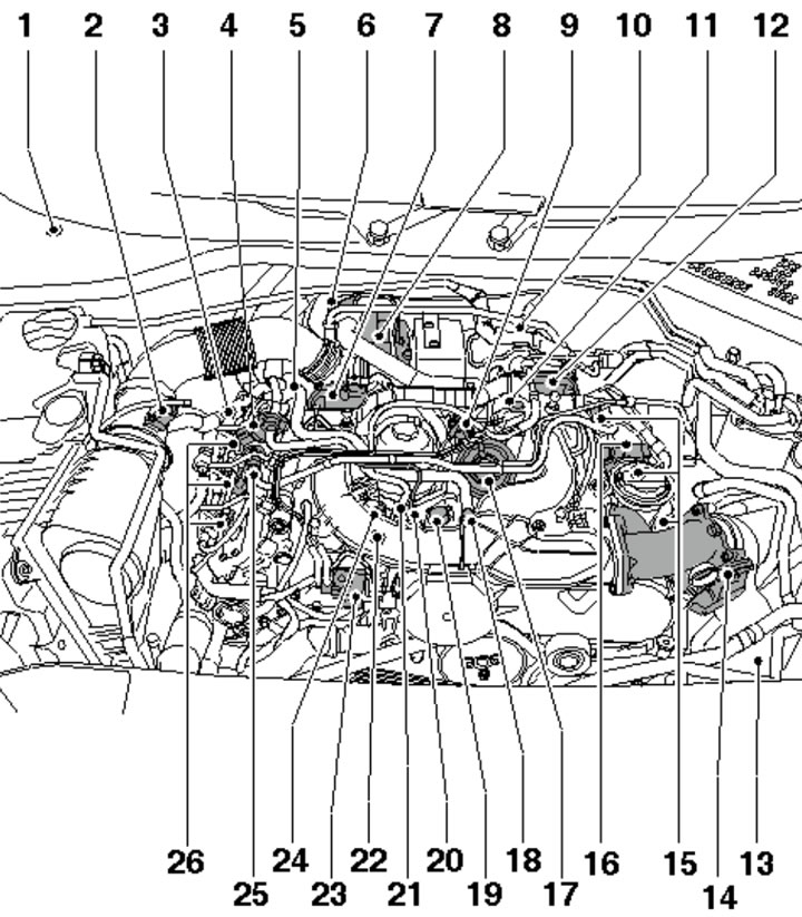
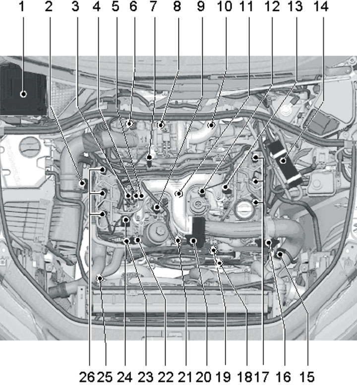
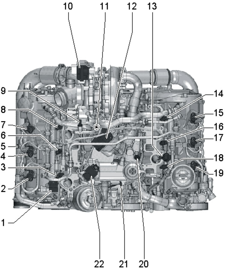
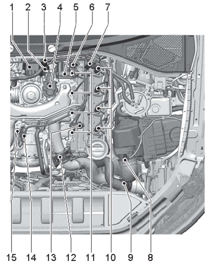
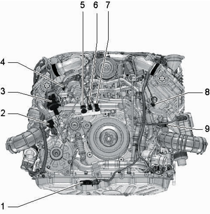
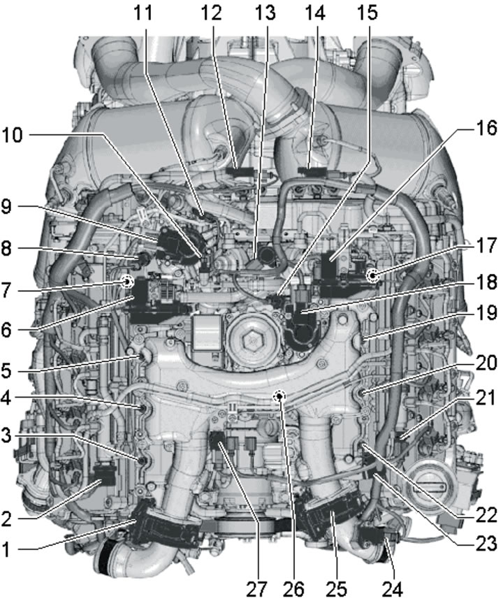
1.1a. Location of fuel system components in the engine compartment of 3.0L models with BUG/BUN engines:
1 - Electronics unit in the air intake chamber;
2 - MAF sensor "G70";
3 - CMP sensor "G40";
4 - Fuel temperature sensor "G81";
5 - Fuel pressure regulation valve "N276";
6 - Lambda probe connector 10 (see illustration 1.1e);
7 - Activator "V157" of the intake manifold flap of cylinder bank No. 1;
8 - Block No. 1 "J724" turbocharger control;
9 - Vacuum block;
10 - Lambda probe "G39" with its heating element "Z19";
11 - EGR cooler switching valve "N345";
12 - Activator "V275" of the intake manifold flap of cylinder bank No. 2;
13 - Boost pressure sensor "G31" with IAT sensor "G42";
14 - Throttle valve module "J338";
15 - Injectors for cylinder bank No. 2;
16 - Fuel pressure sensor "G247";
17 - Mechanical EGR valve;
18 - Return fuel line connection;
19 - Fuel injection pump with gear booster pump;
20 - Connection between the high-pressure fuel pipe and the fuel distribution line of cylinder bank No. 1;
21 - Fuel supply line connection;
22 - Fuel metering valve "N290";
23 - EGR valve "N18";
24 - D/V "F1" engine oil pressure;
25 - 10 bar pressure holding valve in the return fuel line (in the return lines from both rows of cylinders);
26 - Injectors of cylinder bank No. 1.
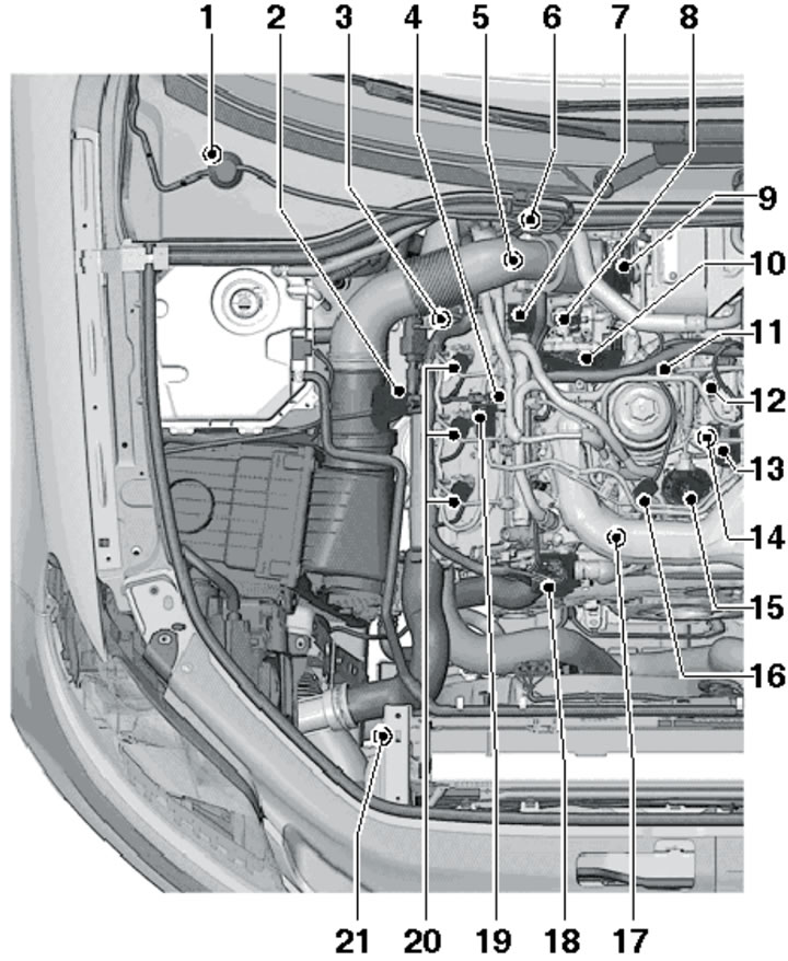
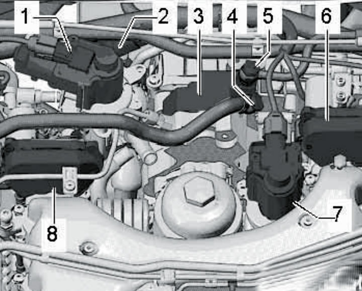
1.1b. Location of fuel system components on the right side of the engine compartment of 3.0L models with CASA/CASB engines:
1 - Electronics unit in the air intake chamber;
2 - MAF sensor "G70";
3 - CMP sensor "G40";
4 - Fuel temperature sensor "G81";
5 - ECT sensor "G62";
6 - Bracket on the wall of the air intake chamber (see illustration 1.1e);
7 - Fuel pressure regulation valve "N276";
8 - Connector of sensor No. 1 "G235" EGR temperature;
9 - Block No. 1 "J724" turbocharger control;
10 - Activator "V157" of the intake manifold flap of cylinder bank No. 1;
11 - EGR temperature sensor connector "G98";
12 - EGR cooler switching valve "N345";
13 - Activator "V338" for EGR adjustment;
14 - EGR temperature sensor "G98";
15 - Fuel injection pump;
16 - Fuel metering valve "N290";
17 - D/V "F1" engine oil pressure;
18 - EGR cooler pump "V400";
19 - 10 bar pressure holding valve in the return fuel line (in the return lines from both rows of cylinders);
20 - Injectors of cylinder bank No. 1;
21 - Sensor "G83" coolant temperature at the radiator outlet.
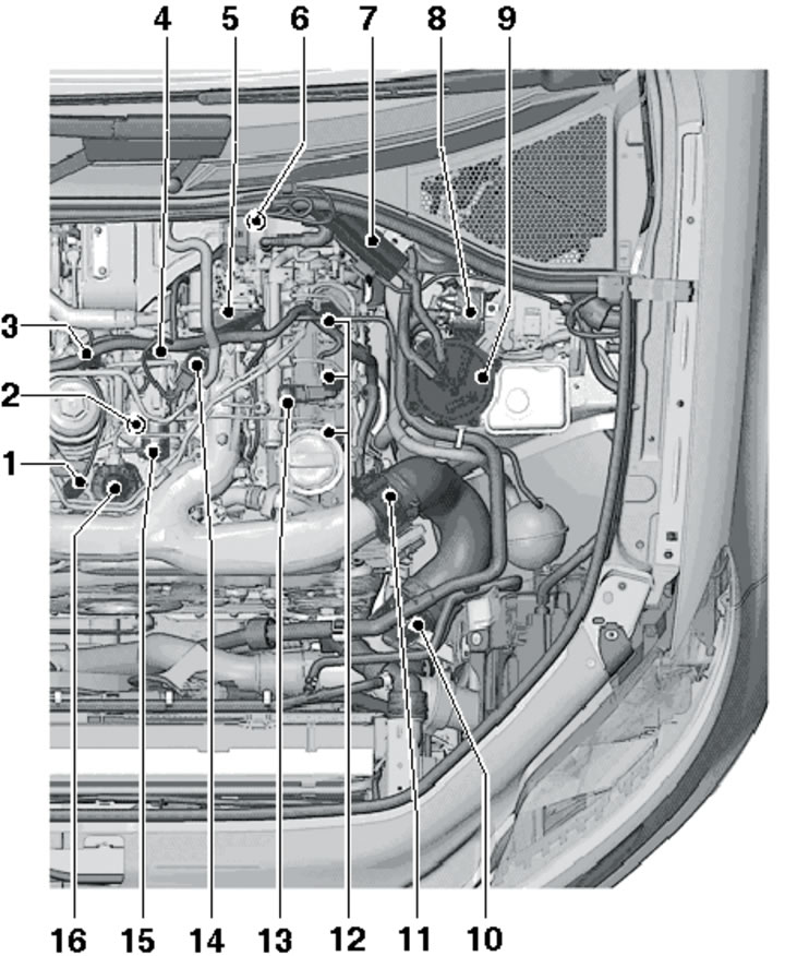
1.1c. Location of fuel system components in the left side of the engine compartment of 3.0L models with CASA/CASB engines:
1 - Fuel metering valve "N290";
2 - EGR temperature sensor "G98";
3 - Sensor connector 2;
4 - Connector of the "V338" activator for EGR adjustment;
5 - Activator "V275" of the intake manifold flap of cylinder bank No. 2;
6 - Lambda probe "G39" with heating element "Z19";
7 - Auxiliary fuel pump "V393";
8 - Fuel cooler;
9 - Fuel filter;
10 - Boost pressure sensor "G31" with IAT sensor "G42";
11 - Throttle valve module "J338";
12 - Injectors for cylinder bank No. 2;
13 - Fuel pressure sensor "G247";
14 - EGR cooler switching valve "N345";
15 - Activator "V338" for EGR adjustment;
16 - Fuel injection pump.
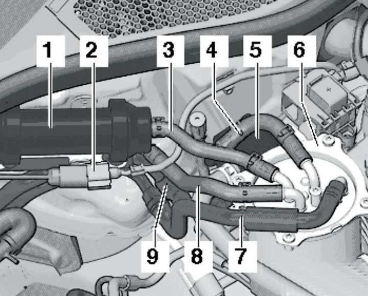
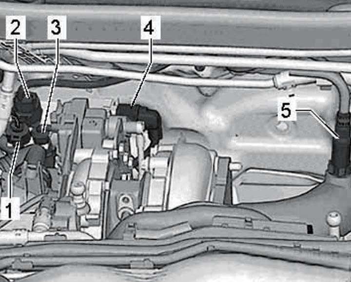
1.1d. Location of components in the fuel filter area of 3.0L models with CASA/CASB, CATA and CCMA engines:
1 - Auxiliary fuel pump "V393" (except for models from the 2011 model year);
2 - Pump connector 1;
3 - Fuel supply line to the high-pressure fuel pump, passing through pump 1;
4 - Fuel return line to cooler 5;
5 - Fuel cooler;
6 - Fuel filter;
7 - Fuel supply line from the tank;
8 - Fuel return line from the high-pressure fuel pump;
9 - Fuel return line to the tank.
1.1e. Details on the bracket in the air intake chamber of 3.0L models with BUG/BUN and CASA/CASB engines and 3.0L SCR models with CATA and CCMA engines:
1 - Engines other than SATA: EGR temperature sensor connector "G98";
1 - SATA engine: connector of sensor No. 2 "G448" EGR temperature;
2 - Lambda probe connector "G39" with heating element "Z19";
3 - BUG/BUN and CASA/CASB engines: EGR sensor No. 1 "G450";
3 - SATA and CCMA engines: differential pressure sensor "G505";
4 - BUG/BUN engines: connector for the "G506" temperature sensor before the diesel particulate filter;
4 - CASA/CASB engines: connector for sensor No. 3 "G495" for exhaust gas temperature;
4 - SATA and SSMA engines: connector of sensor No. 4 "G648" exhaust temperature.
1.1f. Location of fuel system components in the right side of the engine compartment of 3.0L SCR models with SATA and CCMA engines:
1-7 - see captions to illustration 1.1b;
8 - EGR temperature sensor connector "G98";
9 - Connector of sensor No. 1 "G235" EGR temperature;
10 - Block No. 1 "J724" turbocharger control;
11 - Activator "V157" of the intake manifold flap of cylinder bank No. 1;
12 - Fuel injection pump;
13 - Fuel metering valve "N290";
14 - Sensor "F378" low engine oil pressure;
15 - EGR cooler pump "V400";
16 - 10 bar pressure holding valve in the return fuel line (in the return lines from both rows of cylinders);
17 - Injectors for cylinder bank No. 1;
18 - Sensor "G83" coolant temperature at the radiator outlet.
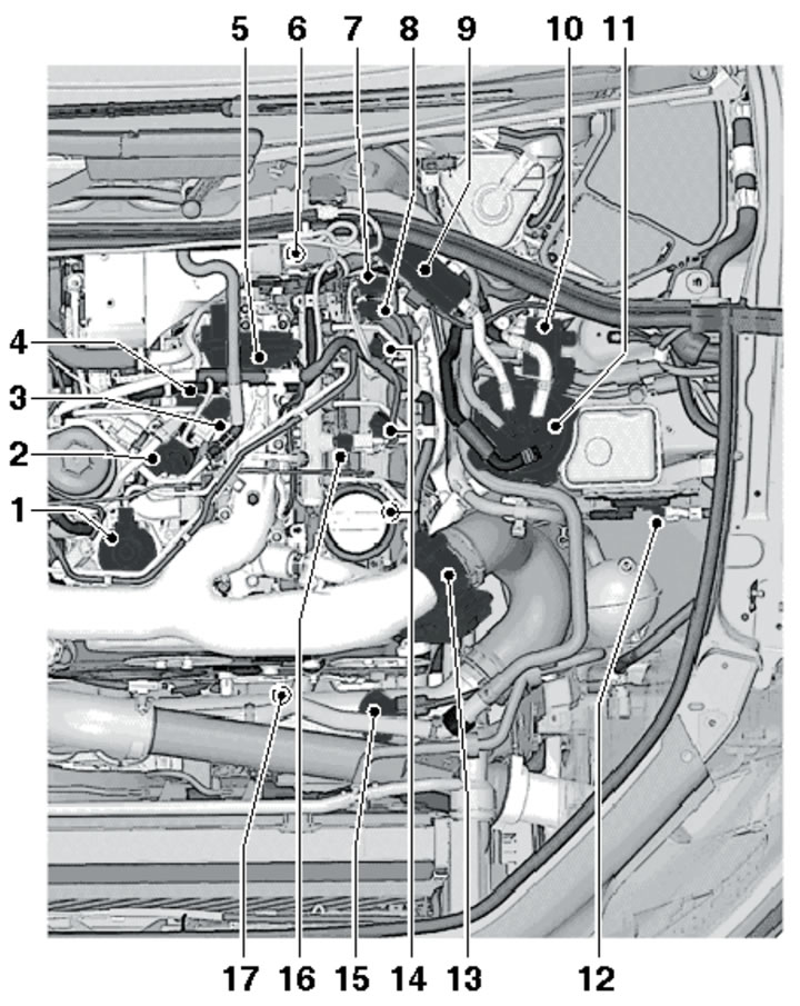
1.1g. Location of fuel system components in the left side of the engine compartment of 3.0L SCR models with SATA and CCMA engines:
1 - High-pressure fuel pump with fuel metering valve "N290";
2 - Activator "V338" for EGR adjustment;
3 - EGR cooler switching valve "N345";
4 - EGR temperature sensor "G98";
5 - Activator "V275" of the intake manifold flap of cylinder bank No. 2;
6 - Sensors on the exhaust pipe (see Part B of this chapter);
7 - Connector of sensor No. 1 "G20" of catalytic converter temperature;
8 - Connector of sensor No. 3 "G495" exhaust gas temperature;
9 - Auxiliary fuel pump "V393" (up to model year 2011);
10 - Fuel cooler;
11 - Fuel filter;
12 - Sensor "G295" of nitrogen oxide concentration (NOx);
13 - Throttle valve module "J338";
14 - Injectors for cylinder bank No. 2;
15 - Boost pressure sensor "G31" with IAT sensor "G42";
16 - Fuel pressure sensor "G247";
17 - D/V "F22" oil pressure and oil pressure regulating valve "N428".
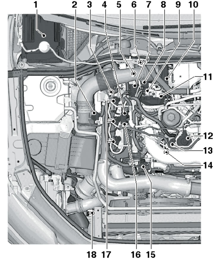
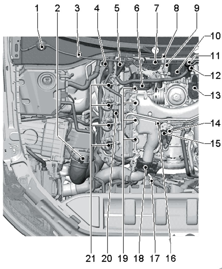
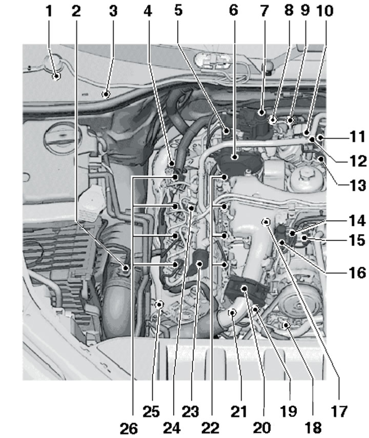
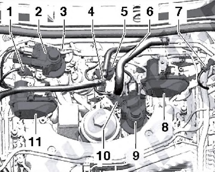
1.1h. Location of fuel system components in the engine compartment of 3.0L models with CJGA/CJGC, CJMA, CLZB and CRCA engines:
1 - ECM "J623";
2 - MAF sensor "G70";
3 - Connector of the EGR temperature sensor "G98";
4 - Connector for thermostat "F265", fuel metering valve "N290" and EGR activator "V338";
5 - Restrictor in the return fuel line;
6 - Bracket on the wall of the air intake chamber (see illustration 1.1k);
7 - Fuel temperature sensor "G81";
8 - Block No. 1 "J724" turbocharger control;
9 - Valve "N489" coolant for cylinder head;
10 - Lambda probe "G39" with its heating element "Z19";
11 - Activator "V338" for EGR adjustment;
12 - ECT sensor "G62";
13 - Fuel pressure sensor "G247";
14 - Fuel filter;
15 - Boost pressure sensor "G31" with IAT sensor "G42";
16 - Throttle valve module "J338";
17 - Injectors for cylinder bank No. 2;
18 - Oil pressure regulating valve "N428";
19 - Temperature sensor "G694" for regulating engine temperature;
20 - Activator "V157" of the intake manifold flap of cylinder bank No. 1;
21 - EGR cooler switching valve "N345";
22 - Low oil pressure sensor "G378";
23 - D/V "F22" oil pressure;
24 - Fuel pressure control valve "N276";
25 - Sensor "G83" coolant temperature at the radiator outlet;
26 - Injectors of cylinder bank No. 1.
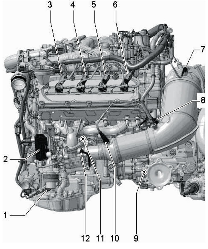
1.1i. Location of fuel system components on the top side of CJGA/CJGC, CJMA, CLZB and CRCA engines (3.0 L models):
1 - Fuel pressure regulation valve "N276";
2 - Injector No. 1 "N30";
3 - Glow plug No. 1 "Q10";
4 - Injector No. 2 "N31";
5 - CMP sensor "G40";
6 - Glow plug No. 2 "Q11";
7 - Injector No. 3 "N32";
8 - Glow plug N93 "Q12";
9 - Fuel temperature sensor "G81";
10 - Block No. 1 "J724" turbocharger control;
11 - Fuel metering valve "N290";
12 - Activator "V338" for EGR adjustment;
13 - Fuel pressure sensor "G247";
14 - Glow plug No. 6 "Q15";
15 - Injector No. 6 "N84";
16 - Glow plug No. 5 "Q14";
17 - Injector No. 5 "N83";
18 - Glow plug No. 4 "Q13";
19 - Injector No. 4 "N33";
20 - ECT sensor "G62";
21 - EGR temperature sensor "G98";
22 - Valve "N489" coolant for cylinder head.
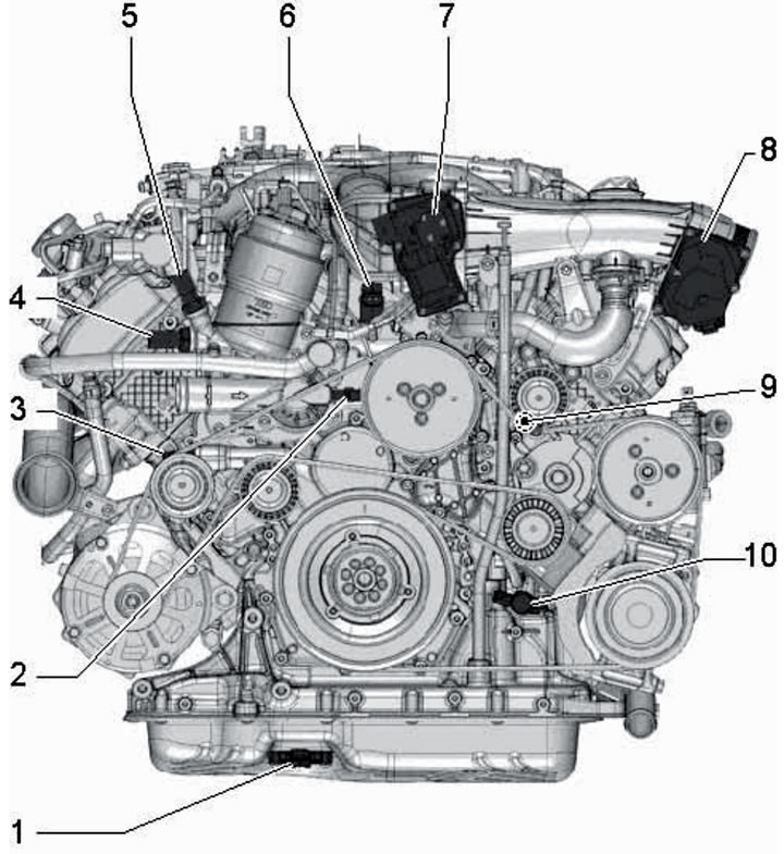
1.1j. Location of fuel system components on the front side of CJGA/CJGC, CJMA, CLZB and CRCA engines (3.0 L models):
1 - Sensor "G266" of engine oil level and temperature;
2 - Thermostat "F265" of the engine cooling system;
3 - Sensor No. 2 "G664" engine oil temperature;
4 - D/V "F22" engine oil pressure;
5 - D/V "F378" low engine oil pressure;
6 - EGR cooler switching valve "N345";
7 - Activator "V157" of the intake manifold flap;
8 - Throttle body module "J338";
9 - Temperature sensor "G694" for regulating engine temperature;
10 - Valve "N428" for regulating engine oil pressure.
1.1k. Connectors and sensors on the bracket on the wall of the air intake chamber of 3.0L models with CJGA/CJGC, CJMA, CLZB and CRCA engines:
1 - Connector of sensor No. 3 "G495" exhaust gas temperature;
2 - Lambda probe connector "G39";
3 - Connector of sensor No. 4 "G648" exhaust temperature (cLZB engine only);
4 - Differential pressure sensor "G505" (only CJGA/CJGC, CJMA and CLZB engines);
5 - Lambda probe "G39".
1.1l. Location of fuel system components on the right side of the engine compartment of 4.2l (BTR) models:
1, 3 - Electronic unit in the air intake chamber;
2 - MAF sensor "G70";
4 - CMP sensor "G40", 9 Nm;
5 - Fuel pressure regulation valve "N276";
6 - Activator "V157" of the intake manifold flap of cylinder bank No. 1;
7 - Activator "V338" of EGR adjustment with position sensor "G212";
8 - Lambda probe connectors;
9 - ECT sensor "G62";
10 - Fuel injection pump;
11 - Fuel supply line connection, 25 Nm;
12 - Fuel return line connection, 25 Nm;
13 - Activator No. 2 "V339" for EGR adjustment with position sensor No. 2 "G466";
14 - Air conditioning compressor connector;
15 - EGR cooler switching valve "N345";
16 - Vacuum block for EGR radiator switching valve;
17 - D/V "F1" pressure and sensor "G8" engine oil temperature;
18 - Throttle body module "J338";
19 - Glow plugs for cylinder bank No. 1;
20 - 10 bar pressure holding valve in the return fuel line (in the return lines from both rows of cylinders);
21 - Injectors of cylinder bank No. 1.
1.1m. Location of fuel system components in the left side of the engine compartment of 4.2L (BTR) models:
1 - Fuel injection pump (up to 1600 bar) with gear booster pump (at 4-5 bar);
2 - Fuel return line connection, 25 Nm;
3 - Fuel supply line connection, 25 Nm;
4 - Activator No. 2 "V339" EGR adjustment with position sensor No. 2 "G466";
5 - Activator "V275" of the intake manifold flap of cylinder bank No. 2;
6 - Connector of the fuel metering valve "N290";
7 - Fuel temperature sensor "G81";
8 - MAF sensor No. 2 "G246";
9 - Boost pressure sensor "G31" with IAT sensor "G42";
10 - Injectors of cylinder bank No. 2;
11 - Glow plugs for cylinder bank No. 2;
12 - Module No. 2 "J544" throttle valve;
13 - Fuel pressure sensor "G247";
14 - Air conditioning compressor wiring connector;
15 - EGR cooler switching valve "N345".
1.1n. Location of fuel system components for 4.2L (BTR) models in the high-pressure fuel pump area:
1 - Activator "V338" for EGR adjustment with position sensor "G212";
2 - ECT sensor "G62";
3 - Fuel injection pump;
4 - Connection of the return fuel line;
5 - Fuel supply line connection;
6 - Activator "V275" of the intake manifold flap of cylinder bank No. 2;
7 - Activator No. 2 "V339" EGR adjustment with position sensor No. 2 "G466";
8 - Activator "V157" of the intake manifold flap of cylinder bank No. 1.
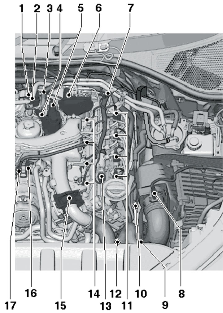
1.1o. Location of fuel system components on the right side of the engine compartment for 4.2L models (CCFA/CCFC):
1, 3 - Electronic unit in the air intake chamber;
2 - MAF sensor "G70";
4 - CMP sensor "G40", 9 Nm;
5 - EGR pressure sensor "G691";
6 - Activator "V157" of the intake manifold flap of cylinder bank No. 1;
7 - Activator "V338" of EGR adjustment with position sensor "G212";
8 - ECT sensor "G62", 2 Nm;
9 - Lambda probe connectors;
10 - Fuel injection pump (up to 2000 bar) with fuel metering valve "N290" and gear booster pump;
11 - Fuel supply line connection;
12 - Return fuel line connection;
13 - Sensor No. 2 "G692" EGR, 25 Nm;
14 - Air conditioning compressor connector;
15 - EGR temperature sensor connector "G98";
16 - EGR cooler switching valve "N345";
17 - Vacuum block for EGR radiator switching valve;
18 - D/V "F378" low pressure, temperature sensor "G8" and D/V "F22" engine oil pressure;
19 - Throttle body module "J338" wiring connector;
20 - Throttle body module "J338"; on the CCFC engine - with flange "Z111" for heating the intake air;
21 - EGR cooler pump "V400";
22 - Glow plugs for cylinder bank No. 1;
23 - Fuel pressure control valve "N276";
24 - Limiter or pressure holding valve of 10 bar in the return fuel line (in the return lines from both rows of cylinders);
25 - Heating element PCV "N79";
26 - Injectors of cylinder bank No. 1.
1.1p. Location of fuel system components in the left side of the engine compartment of 4.2L models (CCFA/CCFC):
1 - Fuel injection pump (up to 2000 bar) with fuel metering valve "N290" and gear booster pump;
2 - Connection of the return fuel line;
3 - Fuel supply line connection;
4 - EGR pressure sensor "G691", 25 Nm;
5 - Activator No. 2 "V339" for EGR adjustment with position sensor No. 2 "G466";
6 - Activator "V275" of the intake manifold flap of cylinder bank No. 2;
7 - Fuel temperature sensor "G81";
8 - MAF sensor No. 2 "G246";
9 - Boost pressure sensor "G31" with IAT sensor "G42";
10 - Heating element No. 2 for PCV "N483";
11 - Injectors for cylinder bank No. 2;
12 - Sensor "G83" coolant temperature at the radiator outlet;
13 - Fuel pressure sensor "G247";
14 - Glow plugs for cylinder bank No. 2;
15 - Module No. 2 "J544" throttle valve; on the CCFC engine - with flange No. 2 "Z112" for heating the intake air;
16 - EGR temperature sensor connector "G98";
17 - Air conditioning compressor wiring connector.
1.1q. 4.2L Front Fuel System Component Locations (CCFA/CCFC):
1 - Sensor "G266" of engine oil level and temperature;
2 - Heating element PCV "N79";
3 - EGR cooler pump "V400";
4 - Sensor "G83" coolant temperature at the radiator outlet;
5 - D/V "F378" low engine oil pressure;
6 - Engine oil temperature sensor "G8";
7 - D/V "F22" engine oil pressure;
8 - Temperature sensor "G694" for regulating engine temperature;
9 - Heating element No. 2 PCV "N483".
1.1r. Location of fuel system components on the left side of 4.2L engines (CCFA/CCFC):
1 - Speed sensor No. 2 "G654";
2 - Turbocharger 2 control unit "J725";
3-6 - Injectors for cylinders No. 5-8 "N83"-"N86";
7 - Sensor No. 4 "G649" EGR temperature, cylinder bank No. 2;
8 - Sensor No. 3 "G497" EGR temperature cylinder bank No. 2;
9 - CKP sensor "G28";
10 - Lambda probe No. 2 "G108" with its heating element No. 2 "Z28";
11 - Valve "N428" for regulating engine oil pressure;
12 - Sensor No. 1 "G236" exhaust gas temperature for cylinder bank No. 2.
1.1s. Location of fuel system components on the right side of 4.2L engines (CCFA/CCFC):
1 - Sensor No. 1 "G235" exhaust gas temperature;
2 - Lambda probe "G39" with its heating element "Z19";
3 - Sensor No. 3 "G495" exhaust gas temperature;
4 - Sensor No. 4 "G648" exhaust gas temperature;
5 - CMP sensor "G40";
6-9 - Injectors for cylinders No. 4-1 "N33"-"N30";
10 - Turbocharger control unit "J724" No. 1;
11 - Speed sensor No. 1 "G653".
1.1t. Location of fuel system components for 4.2L models (CCFA/CCFC) in the high-pressure fuel pump area:
1 - EGR pressure sensor "G691";
2 - Activator "V338" for EGR adjustment with position sensor "G212";
3 - ECT sensor "G62";
4 - Connection of the return fuel line;
5 - High-pressure fuel pump with fuel metering valve "N290";
6 - Fuel supply line;
7 - Fuel temperature sensor "G81";
8 - Activator "V275" of the intake manifold flap of cylinder bank No. 2;
9 - Activator No. 2 "V339" EGR adjustment with position sensor No. 2 "G466";
10 - EGR sensor No. 2 "G692";
11 - Activator "V157" of the intake manifold flap of cylinder bank No. 1.
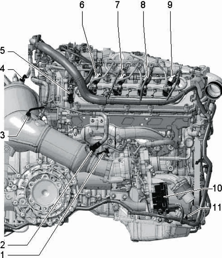
1.1u. 4.2L Engine Top Fuel System Component Locations (CCFA/CCFC):
1 - Throttle body module "J338"; on the CCFC engine - with flange "Z111" for heating the intake air;
2 - Valve "N276" for regulating fuel pressure;
3-5 - Glow plugs No. 1-3 "Q10"-"Q12";
6 - Activator "V157" of the intake manifold flap of cylinder bank No. 1;
7 - Glow plug No. 4 "Q13";
8 - EGR pressure sensor "G691";
9 - Activator "V338" for EGR adjustment;
10 - Fuel temperature sensor "G81";
11 - ECT sensor "G62", 2 Nm;
12 - Differential pressure sensor "G505";
13 - Fuel metering valve "N290";
14 - Sensor No. 2 "G524" differential pressure;
15 - Sensor No. 2 "G692" EGR pressure;
16 - Activator "V275" of the intake manifold flap of cylinder bank No. 2;
17 - Glow plug No. 8 "Q17";
18 - EGR activator No. 2 "V339";
19/20 - Glow plug No. 7/No. 6 "Q16"/"Q15";
21 - Fuel pressure sensor "G247";
22 - Glow plug No. 5 "Q14";
23 - Valve "N489" coolant for cylinder head (only on CCFC engine);
24 - Boost pressure sensor "G31" with IAT sensor "G42";
25 - Module No. 2 "J544" throttle valve; on the CCFC engine - with flange No. 2 "Z112" for heating the intake air;
26 - EGR temperature sensor "G98";
27 - Valve "N345" of the EGR radiator switching valve.
The diagram of the fuel supply system is shown in figures 1.2ad.
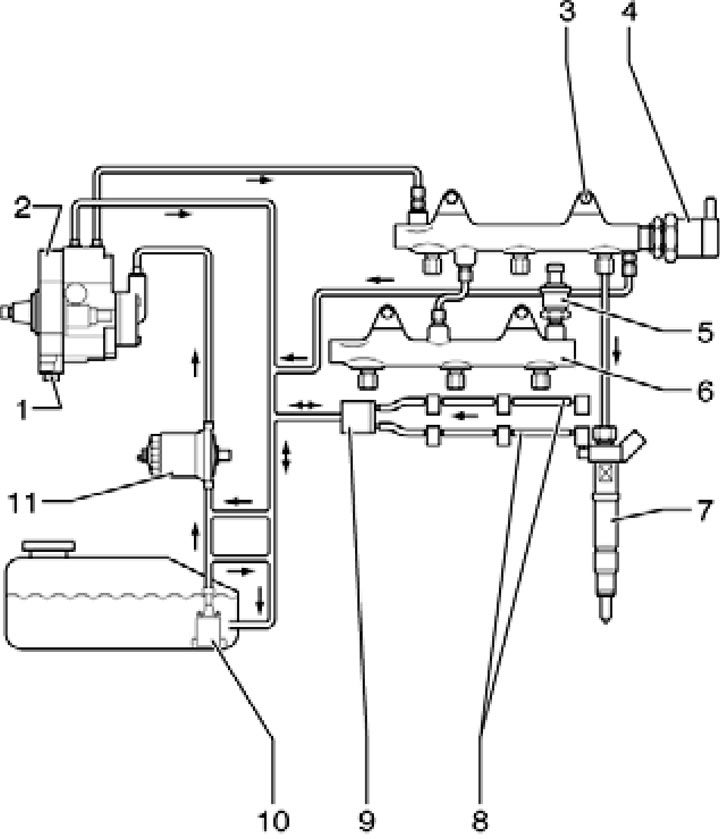
1.2a. Fuel supply system diagram for 3.0L models with BUG/BUN engines:
1 - Fuel metering valve "N290";
2 - Fuel injection pump (up to 1600 bar) with gear booster pump (at 4-5 bar);
3 - Fuel distribution line of cylinder bank No. 1;
4 - Fuel pressure control valve "N276", reinstallation is not permitted;
5 - Fuel pressure sensor "G247", 30 Nm;
6 - Fuel distribution line of cylinder bank No. 2;
7 - Injectors for cylinders No. 1-6;
8 - Fuel return line (return lines and valve 9 are replaced only as an assembly);
9 - 10 bar pressure holding valve in the return fuel line;
10 - Booster pump "G6" 1 bar, in the fuel tank;
11 - Fuel filter.
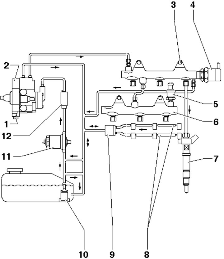
1.2b. Fuel supply system diagram for 3.0 l models with CASA/CASB engines and 3.0 l SCR models with CATA and CCMA engines:
1 - Fuel metering valve "N290", do not unscrew;
2 - Fuel injection pump;
3-11 - See captions for illustration 1.2a;
12- Auxiliary fuel pump "V393" (up to model year 2011).
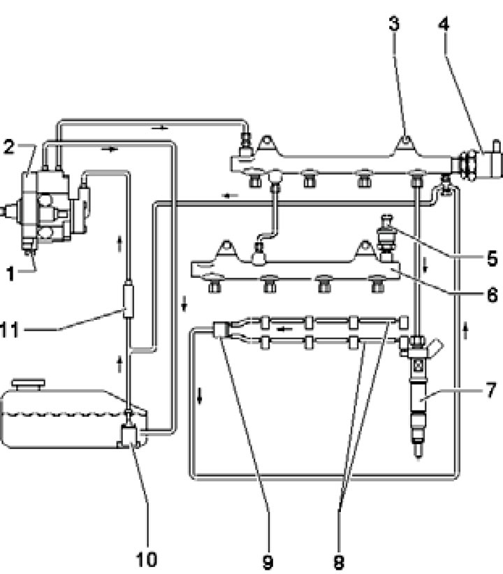
1.2s. Fuel supply system diagram for 3.0L models with CJGA/CJGC, CJMA, CLZB and CRCA engines and 4.2L models with CCFA/CCFC engines:
1 - Fuel metering valve "N290", do not unscrew;
2 - Fuel injection pump;
3 - Fuel distribution line of cylinder bank No. 1;
4 - Fuel pressure control valve "N276", reinstallation is not permitted;
5 - Fuel pressure sensor "G247": 60 Nm, then loosen by 90° (3.0 L models) or 180° (4.2 L models), then tighten to a force of 85 Nm;
6 - Fuel distribution line of cylinder bank No. 2;
7 - Nozzle;
8 - Fuel return line, do not disassemble;
9 - Limiter (on the CCFA engine - a pressure holding valve at 10 bar) to maintain low residual pressure in return lines; replaced only together with the fuel return lines;
10 - Booster pump "G6" 1 bar, in the fuel tank;
11 - Fuel filter.
1.2d. Fuel supply system diagram for 4.2L models with BTR engine:
1-4, 6-8, 10-11 - See captions for illustration 1.2c;
5 - Fuel pressure sensor "G247"; 35 Nm;
9 - Fuel pressure holding valve 10 bar in return lines; replaced only together with the fuel return lines.
The components of the fuel injection system are shown in Figures 1.3a-e.
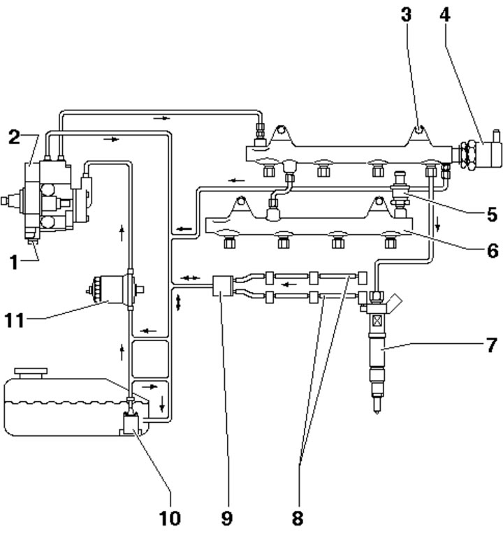
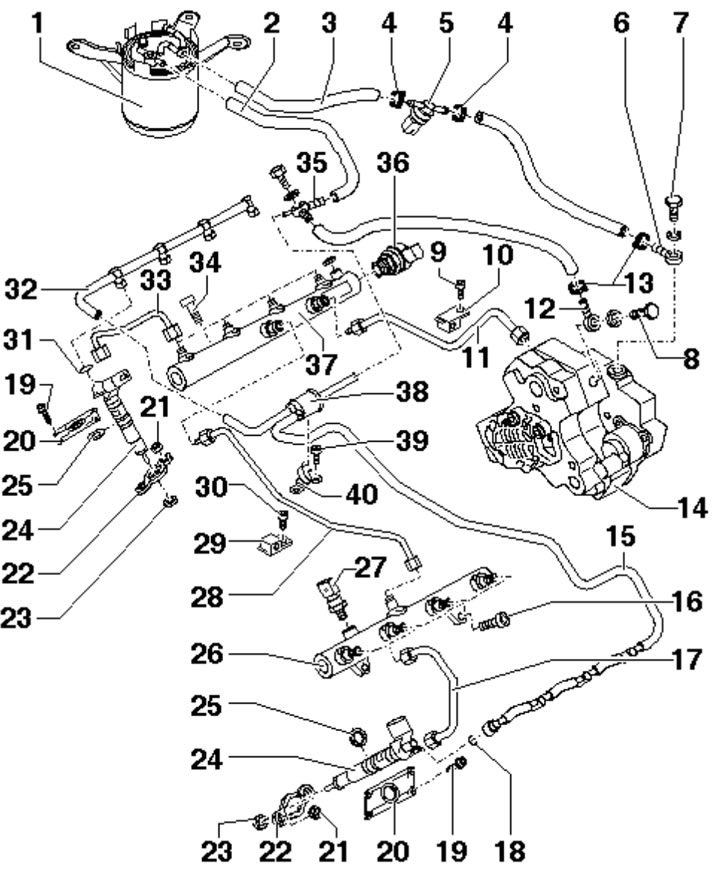
1.3a. Fuel injection system details for 3.0L models with BUG/BUN engines:
1 - Bracket with fuel filter;
2 - Return fuel line;
3 - Fuel supply line;
4 - Hose clamp;
5, 8 - Hollow bolt for fuel return line, 25 Nm;
6 - Fuel temperature sensor "G81";
7 - Fuel pressure control valve "N276", reinstallation is not permitted;
9 - Hollow bolt for fuel supply line, 25 Nm;
10 - High pressure fuel pipe (between the fuel injection pump and highway 25), 25 Nm;
11 - High pressure fuel pipe (between highways 25 and 23), 25 Nm;
12 - High-pressure fuel pump with fuel metering valve "N290";
13, 26 - Return fuel lines, do not separate from valve 28;
14 - Casing bolt 15, 5.5 Nm;
15 - Injector housing;
16 - Seals;
17 - Retaining part: reinstallation is only permitted with the same injector and only on the same cylinder: when replacing the injector, this part must also be replaced;
18 - Nut of part 17, 10 Nm;
19 - Injector, do not swap when reinstalling;
20 - Bolt, 22 Nm;
21 - High pressure pipes for cylinder bank No. 2, 25 Nm;
22 - Fuel pressure sensor "G247", screwed into line 23 with a force of 30 Nm;
23 - Fuel distribution line of cylinder bank No. 2;
24 - High pressure pipes of cylinder bank No. 1;
25 - Fuel distribution line of cylinder bank No. 1;
27 - Holder;
28 - Fuel pressure holding valve in return lines 13 and 26, approximately 10 bar;
29 - Common fuel return line to the tank.
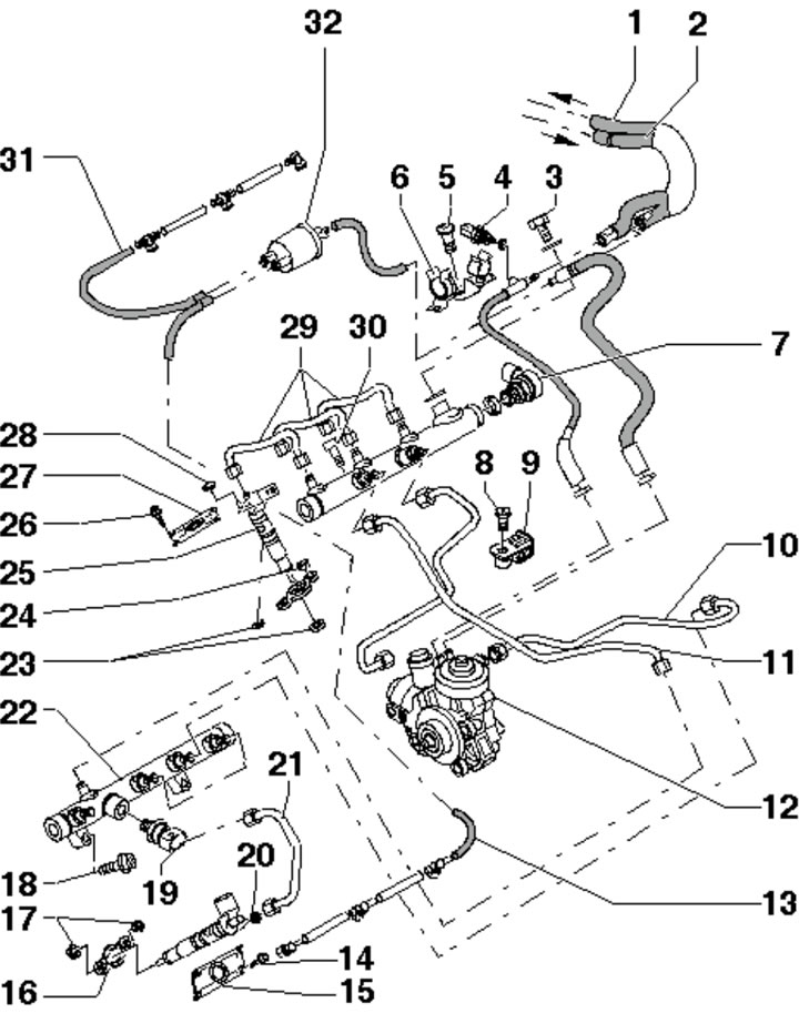
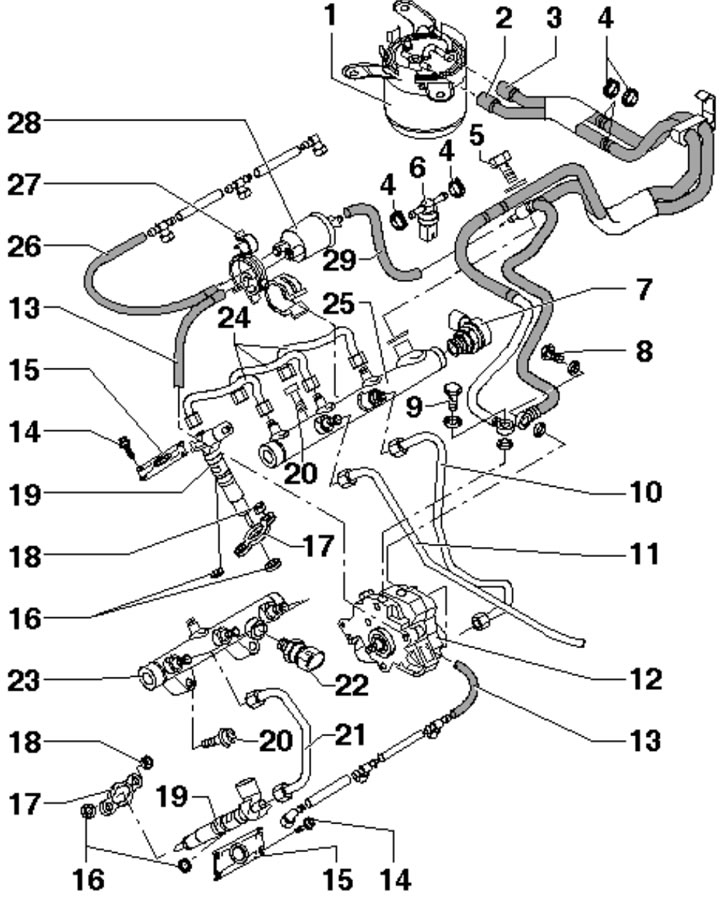
1.3b. Fuel injection system parts for 3.0L models with CASA/CASB engines and 3.0L SCR models with CATA and CCMA engines:
1 - Fuel return line to the tank;
2 - Fuel supply line from the filter;
3 - Hollow bolt for fuel return line, 25 Nm;
4 - Fuel temperature sensor "G81";
5, 8 - Bolt;
6, 9 - Bracket;
7 - Fuel pressure control valve "N276", reinstallation is not permitted;
10 - High pressure fuel pipe (between the fuel injection pump and highway 22);
11 - High pressure fuel pipe (between fuel distribution lines);
12 - High-pressure fuel pump with fuel metering valve "N290";
13, 31 - Return fuel lines, do not separate from valve 32;
14 - Casing bolt 15, 5.5 Nm;
15, 27 - Injector housing;
16 - Retaining part: reinstallation is only permitted with the same injector and only on the same cylinder: when replacing the injector, this part must also be replaced;
17, 24 - Nut of part 16, 10 Nm;
18 - Main line bolt 22, 22 Nm;
19 - Fuel pressure sensor "G247", screwed into line 22 with a force of 30 Nm;
20, 23, 28 - Seals, subject to replacement;
21 - High pressure pipes for cylinder bank No. 2, 25 Nm;
22 - Fuel distribution line of cylinder bank No. 2;
25 - Injector, do not swap when reinstalling;
26 - Casing bolt 27, 5.5 Nm;
29 - High pressure pipes for cylinder bank No. 1, 25 Nm;
30 - Fuel distribution line bolt No. 1, 22 Nm;
32 - Fuel pressure holding valve in return lines 13 and 31, approximately 10 bar.
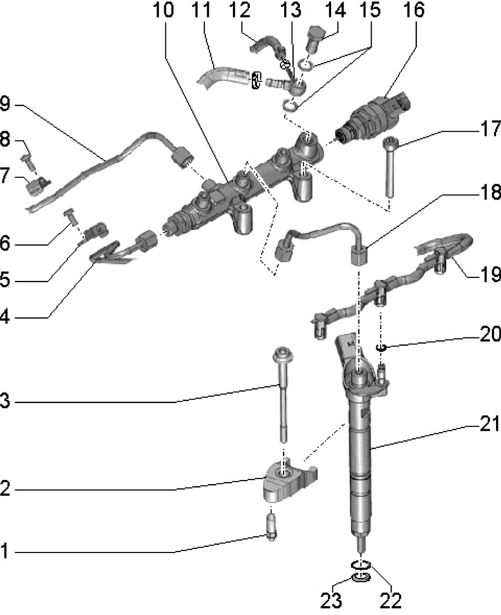
1.3c. Fuel injection system details for 3.0L models with CJGA/CJGC, CJMA, CLZB and CRCA BTR engines:
1 - Support of part 2; it is fastened to the camshaft bed with a force of 2.5 Nm, and to the cylinder head with a force of 9 Nm;
2 - Nozzle retaining part; reinstallation is only permitted with the same injector and only on the same cylinder; when replacing the injector, this part must also be replaced;
3 - Bolt, 14 Nm;
4 - High pressure fuel pipe (between the fuel injection pump and highway 10);
5, 7 - High pressure tube holder;
6, 8 - Bolt, 9 Nm;
9 - High pressure fuel pipe (between fuel distribution lines);
10 - Fuel distribution line;
11 - Fuel return hose to the tank;
12, 19 - Fuel return hose from injectors, do not disassemble;
13 - Hose ring connection;
14 - Hollow bolt, 25 Nm;
15 - Seals, subject to replacement;
16 - Fuel pressure control valve "N276" with deformable sealing lip, reinstallation is not permitted;
17 - Bolt, 22 Nm;
18 - High pressure pipe from the fuel distribution line to the injector, 25 Nm;
20, 22 - Sealing ring, subject to replacement;
21 - Nozzle;
23 - Copper seal, must be replaced.
1.3d. Fuel injection system details for 4.2L models with BTR engine:
1 - Bracket with fuel filter;
2/3 - Fuel supply/return line;
4, 13 - Clamp;
5 - Fuel temperature sensor "G81", 2 Nm;
6 - Connection of the fuel supply line to the high-pressure fuel pump;
7 - Hollow bolt connecting the fuel supply line, replace the seals, 25 Nm;
8 - Hollow bolt connecting the return fuel line, replace the seals, 25 Nm;
9, 30 - Bracket bolt 10/29, 10 Nm 10.29 High pressure pipe bracket;
11 - High pressure fuel pipe (between the fuel injection pump and highway 37);
12 - Connection of the return fuel line to the high-pressure fuel pump;
14 - Fuel injection pump (up to 1600 bar), with gear booster pump (at 4-5 bar);
15, 32 - Fuel return lines, do not disassemble;
16, 34 - Bolt, 22 Nm;
17 - High-pressure fuel lines for cylinder bank No. 2, 25 Nm;
18 - Sealing ring, must be replaced;
19 - Casing bolt 20, 5.5 Nm;
20 - Injector housing, 5 Nm;
21 - Nut of part 22, 10 Nm;
22 - Nozzle retaining part; reinstallation is only permitted with the same injector and only on the same cylinder; when replacing the injector, this part must also be replaced;
23, 25 - Seal;
24 - Nozzle;
26 - Fuel distribution line of cylinder bank No. 2;
27 - Fuel pressure sensor "G247", screwed into the line 26, 35 Nm;
28 - High-pressure fuel lines between lines 26 and 37;
31 - Fuel return line connection sealing ring, must be replaced;
33 - High-pressure fuel lines for cylinder bank No. 1, 25 Nm;
35 - Tee connection of return fuel lines, with hollow bolt, replace O-rings;
36 - Fuel pressure control valve "N276", reinstallation is not permitted;
37 - Fuel distribution line of cylinder bank No. 1;
38 - Pressure limiter or pressure holding valve in return fuel lines;
39 - Bolt;
40 - Valve retainer 38.
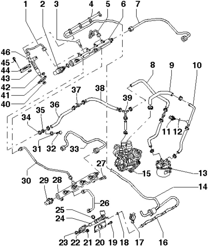
1.3e. Fuel injection system details for 4.2L models with CCFA/CCFC engines:
1, 5 - High-pressure fuel lines for cylinder bank No. 1, 25 Nm;
2 - Fuel pressure control valve "N276", reinstallation is not permitted;
3, 27 - Bolt, 22 Nm;
4, 16 - Fuel return lines, do not disassemble;
6 - Fuel distribution line of cylinder bank No. 1;
7 - High pressure fuel pipe (between the fuel injection pump and highway 6);
8 - Fuel return line, between the fuel injection pump and the fuel filter;
9, 10 - Fuel supply lines, between the high-pressure fuel pump and the fuel filter;
11 - Fuel temperature sensor "G81", 2 Nm;
12, 25, 43, 46 - O-ring, subject to replacement;
13 - Bracket with fuel filter;
14 - Return fuel lines between cylinder banks;
15 - High-pressure fuel pump, with fuel metering valve "N290";
17 - Fuel return line holder;
18 - Fuel return line connection sealing ring, must be replaced;
19/45 - Casing bolt 20/44, 5.5 Nm;
20, 44 - Injector housing, 5 Nm;
21 - Nut of part 22, 10 Nm;
22, 41 - Nozzle retaining part; reinstallation is only permitted with the same injector and only on the same cylinder; when replacing the injector, this part must also be replaced;
23, 31, 34 - Gasket, subject to replacement;
24, 42 - Injector;
25 - High-pressure fuel lines for cylinder bank No. 2, 25 Nm;
28 - Fuel distribution line of cylinder bank No. 2;
29 - Fuel pressure sensor "G247", screwed into line 28;
30 - High pressure fuel lines between lines 28 and 6;
32 - Hollow bolt connecting the fuel return line, 25 Nm;
33 - High pressure fuel pipe (between the fuel injection pump and highway 28);
35 - Hollow joint;
36, 38 - Return fuel line;
37 - T-joint;
39 - T-shaped connection of return fuel lines;
40 - Sealing.
The components of the vacuum section of the fuel system of the 3.0 l 2nd generation engines are shown in Figure 1.4.
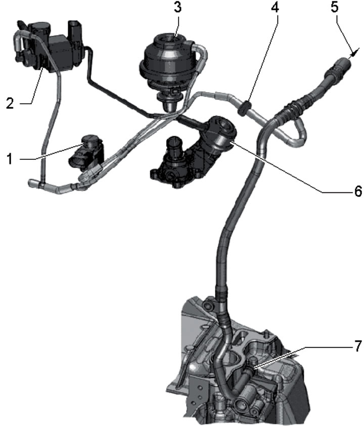
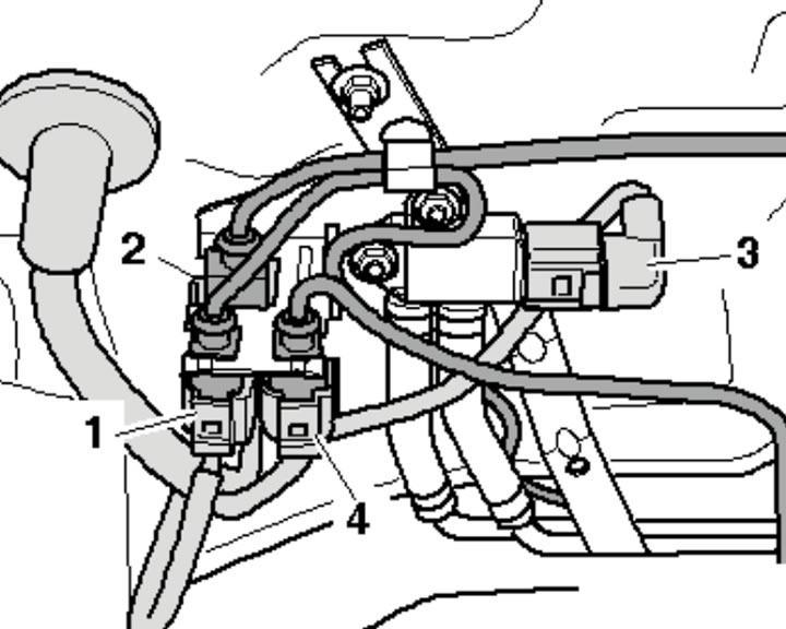
1.4. Details of the vacuum section of the fuel system of 3.0 l 2nd generation engines:
1 - EGR cooler switching valve "N345";
2 - Valve "N489" coolant for cylinder head;
3 - Vacuum block for EGR cooler;
4 - Non-return valve;
5 - To the brake booster;
6 - Coolant supply shut-off valve;
7 - Vacuum connection on top of oil pan, to vacuum pump.
The fuel tank contains one or two fuel delivery modules, each of which is an assembly of two fuel level sensors and a fuel pump with a mesh filter. Fuel gauges are designed to display the fuel level on the instrument cluster. The electric fuel pump is designed to create pressure in the low-pressure part of the fuel supply system. The mesh fuel filter is designed to last the entire life of the vehicle and does not require replacement.
Jet pumps are designed to keep the trays in which the fuel supply modules are placed constantly filled with fuel, so that under no circumstances does air enter the fuel system.
The fuel booster pump is designed to supply fuel from the low-pressure circuit to the high-pressure fuel pump under a pressure of at least 5 bar, which is necessary for the operation of the high-pressure fuel pump in any mode.
The high-pressure fuel pump increases the fuel pressure to a maximum of 1600 bar or 2000 bar and delivers it through one pipe to the fuel distribution line of one cylinder bank, which is connected to the line of the other cylinder bank. In the distribution lines, the fuel pressure is equalized for all injectors and is monitored by a fuel pressure sensor.
Pressure fuel lines (metal tubes) manufactured with pre-set lengths and bending radii in the required locations; such fuel lines should be installed in such a way that they are not subject to any stress.
The injectors inject fuel under high pressure directly into the combustion chambers. The moment and duration of fuel injection are determined by the ECM unit based on signals from various sensors (see Section 2).
Excess fuel from the injectors is returned to the fuel tank through the injector return lines, the pressure holding valve and the fuel pump. The fuel pressure holding valve is designed to maintain the pressure in the return lines of the injectors, which is necessary for the operation of the injectors. Do not disconnect the fuel pressure holding valve while the engine is running to prevent damage to the injectors. The return fuel lines of the injectors are replaced only together with the pressure holding valve. If the fuel retention valve and fuel return lines from the injectors have been replaced, after starting the engine, allow it to idle for approximately two minutes to purge air from the fuel system.
Rail-mounted fuel injection system "Common Rail", compared to the injection system with a distributor fuel injection pump, it has the following distinctive features:
- The injection pressure can be freely selected and adapted to the corresponding engine operating mode;
- High injection pressure (up to 1600 or 2000 bar) creates conditions for good mixture formation;
- Flexible batch injection process with multiple pre- and post-injections;
- Low fuel consumption;
- Low level of harmful emissions;
- Smooth running engine.
Injection system "Common Rail" it involves a variety of injection control algorithms in order to adapt the pressure and injection process to the engine operating mode. At the same time, such a system fully complies with the ever-increasing demands for reduced fuel consumption, reduced levels of harmful emissions and increased engine smoothness.
Fuel saving tips
Driving style has a significant impact on fuel consumption. Below are some tips to help you save fuel.
- After starting the engine, move off immediately, even if it is in cold weather (do not allow a cold engine to run at high speeds and do not drive at high speeds until the engine has warmed up).
- If you stop the vehicle for more than 40 seconds, turn off the engine.
- Always drive in the highest gear possible for the given speed.
- When driving long distances, maintain a steady speed whenever possible. Avoid driving at high speeds, do not brake unnecessarily.
- Do not carry unnecessary loads in your vehicle.
- Check the air pressure in your tires and do not allow the pressure to drop excessively.
Air supply
The air supply system includes the air intake, air cleaner, throttle body, intake manifold, turbocharger and intercooler, as well as (see Part B) eGR and PCV systems.
Each throttle valve is controlled by the ECM via an electric motor based on a signal from the accelerator pedal position sensor. The throttle position is controlled by the TPS sensor. On diesel models, the throttle body has the following functions.
- In some modes, the throttle valve is used to create a pressure differential between the intake tract and the EGR circuit. This pressure differential promotes more efficient operation of the EGR system.
- In DPF regeneration mode, the throttle valve regulates the inlet air flow.
- When the engine is turned off, the damper closes, gradually reducing the amount of incoming air to smoothly stop the engine.
All diesel engines use turbocharging, with charge air cooling by an intercooler. The turbocharger consists of two elements (turbines and compressors), mounted on one shaft and enclosed in a common housing. The turbocharger bearings receive oil for cooling and lubrication from the engine through the supply oil line. The oil returns to the crankcase through the return oil line.
The turbocharger increases the pressure of purified atmospheric air, thereby increasing the amount of air entering the cylinder in one cycle. With more oxygen, more fuel can be burned. Thus, with the same working volume and rotation speed characteristics, better power figures are achieved. The air heated in the turbocharger is cooled as it passes through the intercooler. When cooling, the air density increases and, since more oxygen enters the combustion chambers, an additional increase in power occurs.
Ensuring safety and maintaining cleanliness when working with the fuel supply system
Caution: Fuel injection equipment is manufactured to very precise tolerances and with very small clearances, so absolute cleanliness is especially important when working with these components. Be sure to insert plugs into any open holes or lines.
Caution: When loosening and tightening the union nuts securing the fuel pressure lines, simultaneously press the flared end of the fuel line against the injector and remove (suck) vacuum removal to prevent dirt from entering the fuel system. Avoid allowing the union nuts to strike the flared edges of the new fuel lines, as this may damage the lines and introduce foreign particles into the lines. Close the holes formed after disconnecting the tubes with clean plugs.
- Do not work on the fuel system near an open flame, do not smoke, and do not use heating devices while working on the fuel system! Keep a fire extinguisher handy.
- Before working on the fuel system, always disconnect the negative battery cable to avoid sparks. Before disconnecting the battery, you should read the fault codes (see Chapter 5).
- Ensure proper ventilation of the workplace - fuel vapors are toxic.
- The fuel system is under pressure and fuel may escape if opened, so wear safety glasses. Wipe up any spilled fuel with a rag.
- Hose connections are secured using strap or clamp clamps. When disassembling, the clamping clamps should be replaced with band clamps.
- Clean connections and adjacent areas thoroughly before opening.
- Place the removed components on a clean surface and cover with plastic, paper or a lint-free cloth.
- Close open nipple connectors, for example, with suitable clean plugs.
- Install only clean parts - remove replacement components from packaging immediately before installation. Do not use parts that have been stored without packaging.
- Avoid using compressed air when the fuel system is open and try not to move the vehicle if possible.
- Do not use sealants containing silicone, as silicone particles that get into the engine do not burn off and may cause the lambda probes to fail.
- Before removing the fuel tank, pump out the fuel from it using a pump specially designed for this purpose.
- Remember that even an empty fuel tank remains explosive.
- After installing the fuel system components, start the engine and check all connections for leaks.