
Table of contents: 3.0L 1st generation engines (BUG/BUN) ↓ 3.0L 1st generation engines… ↓ 3.0L SCR engines (SATA, SSMA) ↓ 3.0L 2nd generation engines… ↓ 4.2L engines ↓
Note: If a mechanical fault is detected in the turbocharger (for example, damage to compressor blades), in addition to replacing the turbocharger assembly itself, to prevent further damage, you should ensure that the air supply tract is clean and free of foreign objects. If foreign objects are found in the boost system, the boost air lines should be cleaned and the intercooler should be replaced.
3.0L 1st generation engines (BUG/BUN)
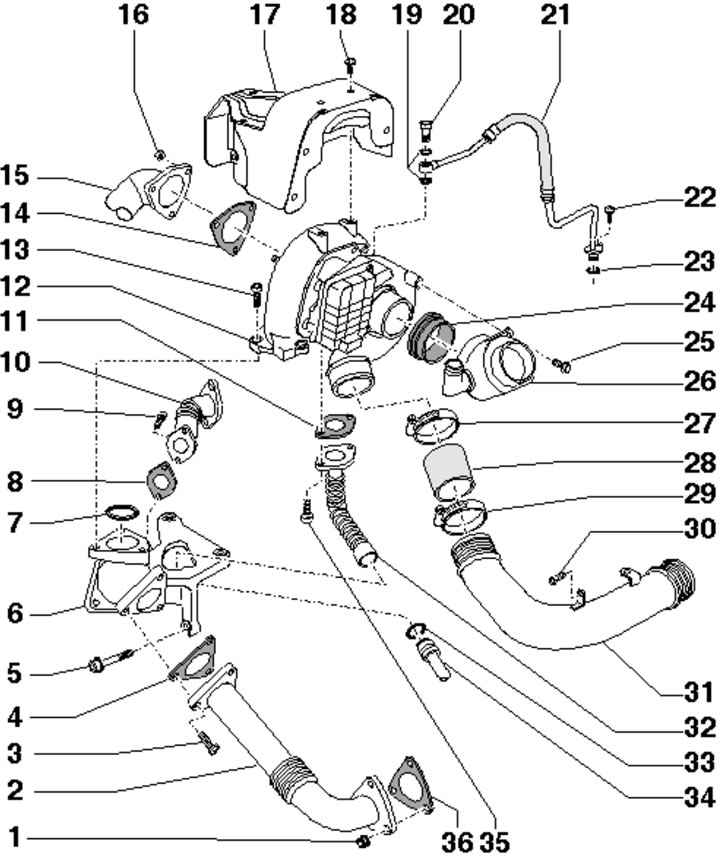
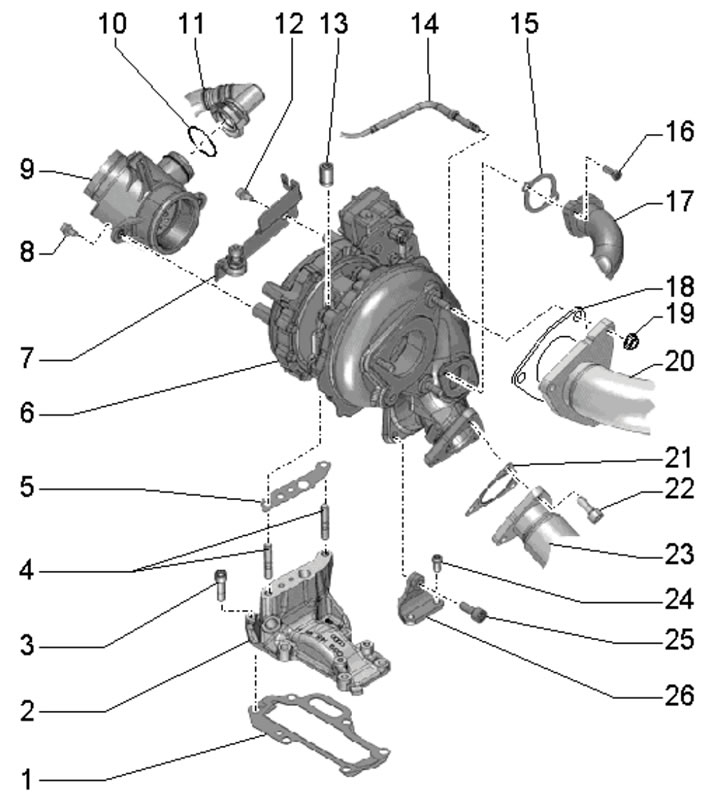
1. Turbocharger installation details are shown in the illustration.
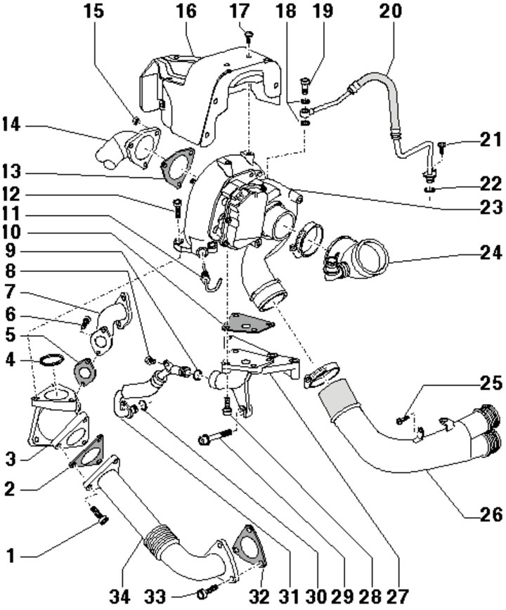
5.1. Details of turbocharger installation for BUG/BUN engines:
1 - Bolt;
2, 4, 5, 10, 13, 18, 32 - Gasket, subject to replacement;
3 - Intermediate flange;
6* - Bolt, 9 Nm;
7 - Connecting tube to the EGR radiator switching valve;
8, 17, 21, 25 - Bolt, 9 Nm;
9, 22, 30 - O-ring, subject to replacement;
11* - Sensor No. 1 "G235" exhaust gas temperature;
12* - Bolt, to be replaced, 30 Nm, then tighten to an angle of 90°;
14 - Primary catalytic converter;
15* - Bolt, 23 Nm;
16 - Turbocharger heat shield;
19 - Hollow bolt, 15 Nm;
20 - Oil supply line from the cylinder block;
23 - Turbocharger with control unit No. 1 "J724";
24 - Connecting part of the intake air hose, from the MAF sensor "G70" to the turbocharger;
26 - Right air tube;
27 - Turbocharger bracket;
28* - Bolt, 20 Nm;
29 - Bolt, 25 Nm;
31 - Return oil line to the cylinder block;
33 - Bolt with nut;
34 - Intermediate tube.
Parts marked with "*" should be lubricated with high temperature grease before installation/tightening. Removing the compressor control unit requires a special electronic diagnostic tool, so this procedure is not described.
2. Drain the coolant (see Chapter 3), remove the primary catalytic converter (see Part B) and the right rear coolant pipe (see Chapter 3).
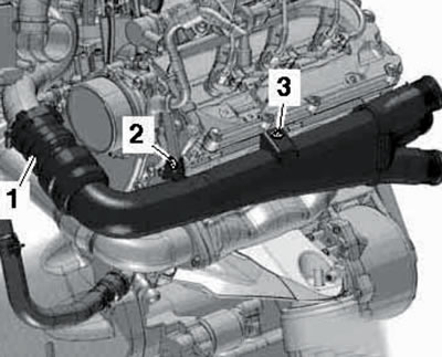
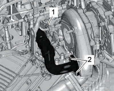
3. Disconnect the connector (2 in the illustration), unscrew the hollow bolt (3) and disconnect the oil supply line from the turbocharger.
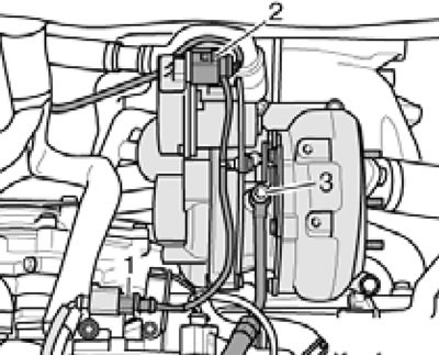
5.3. Connector (2) and hollow bolt (3).
4. Remove the connector from the bracket (1 in illustration 1.1e) exhaust gas temperature sensor No. 1 "G235" disconnect the connector and move the wiring to the side.
5. Remove the bolts (see illustration) and remove the turbocharger from the connecting flange.
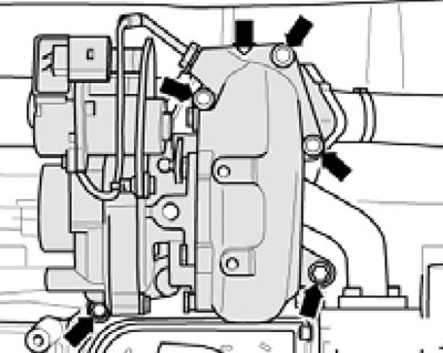
5.5. Turbocharger mounting bolts.
6. If necessary, after removing the turbocharger, you can unscrew the bolts (see illustration) and remove the intermediate flange with the EGR connecting pipe.
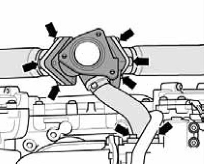
5.6. Intermediate flange fastening bolts.
7. Installation is carried out in reverse order. Use new sealing parts. Fill the turbocharger with oil through the oil supply line. After installation, let the engine idle for about a minute to ensure the compressor receives sufficient lubrication.
3.0L 1st generation engines (CASA/CASB)
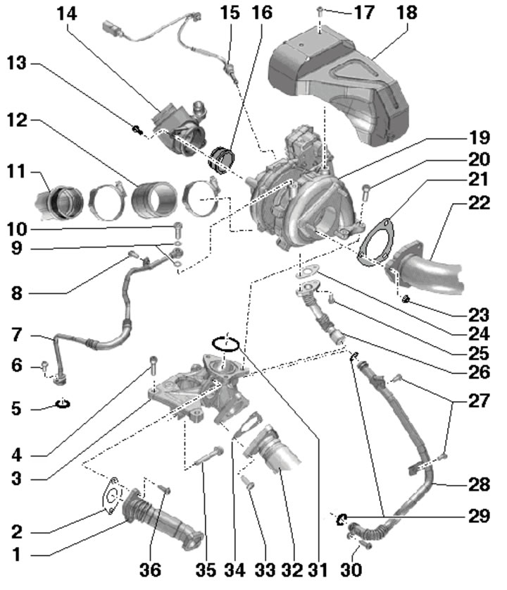
8. Turbocharger installation details are shown in the illustration.
5.8. CASA/CASB engine turbocharger installation details:
1 - Nut;
2 - Intermediate tube;
3, 13 - Bolt*, to be replaced, 30 Nm, then tighten to an angle of 90°;
4, 7, 8, 11, 14, 19, 36 - Gasket, subject to replacement;
5 - Bolt, 25 Nm;
6 - Intermediate flange;
9, 35- Bolt*, 9 Nm;
10 - Connecting tube to the EGR radiator switching valve;
12 - Turbocharger with control unit No. 1 "J724";
15 - Primary catalytic converter;
16* - Bolt, 23 Nm;
17 - Turbocharger heat shield;
18, 22, 25, 30 - Bolt, 9 Nm;
20 - Hollow bolt, 15 Nm;
21 - Oil supply line from the cylinder block;
23, 33 - Sealing ring, subject to replacement;
24 - Gasket;
26 - Connecting part of the intake air hose, from the MAF sensor "G70" to the turbocharger;
27, 29 - Reinforced clamp, 5.5 Nm;
28 - Air hose from turbocharger to right air pipe;
31 - Right air tube;
32 - Upper part of the return oil line from the turbocharger;
34 - Lower part of the return oil line, to the cylinder block.
Parts marked with "*" should be lubricated with high temperature grease before installation/tightening. Removing the compressor control unit requires a special electronic diagnostic tool, so this procedure is not described.
9. Remove the upper engine cover (see Section 19 of Chapter 1).
10. Remove the air hose (see illustration 15.6 Chapter 2).
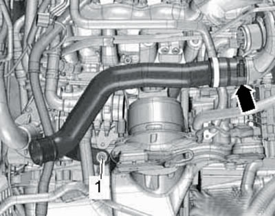
11. Remove the bolts (left arrows in the illustration) connection and slide it to the side with the air intake hose connected (right arrow).
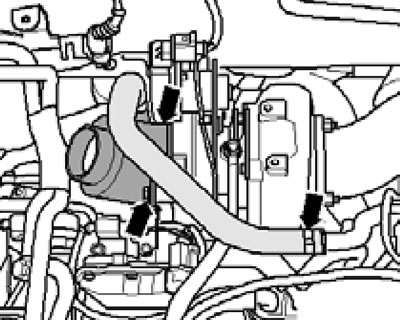
5.11. Fasteners and hose on the air supply connection.
12. Disconnect the vacuum hose going to the vacuum pump (see illustration 4.26 Chapter 2).
13. Remove the bolts (1 in illustration 4.60 Chapter 2) and loosen the bolt (3). Move the vacuum hose with the bracket (2) to the side and remove the turbocharger heat shield.
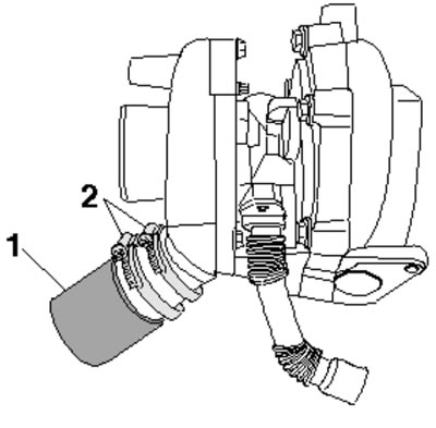
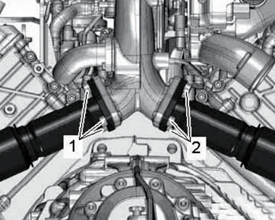
14. Remove the bolts (2 and 3 in the illustration), loosen the clamp (1) and remove the air pipe from the turbocharger.
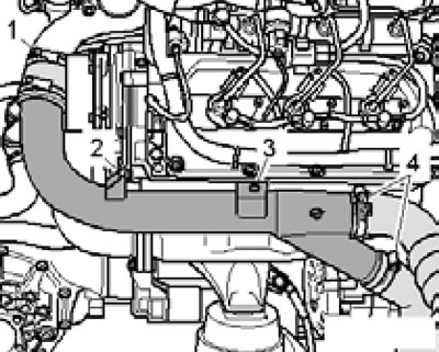
5.14. Removing the air tube from the turbocharger.
15. Disconnect the connector (1 in illustration 3.2 Chapter 2) turbocharger "V280" activator and disconnect the oil supply line (2) from the turbocharger.
16. Remove the connector from the bracket (1 in illustration 1.1e) sensor No. 1 "G235" exhaust gas temperature.
17. Move the lambda probe wiring aside and remove the nuts (see illustration 4.61 Chapter 2) fastening the primary catalytic converter to the turbocharger and pull the catalytic converter to the side.
18. Remove the turbocharger mounting bolts (see illustration).
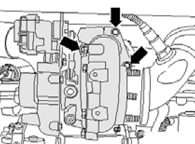
5.18. Turbocharger fasteners.
19. Upper part of the return oil pipe (1 in the illustration) is secured to the turbocharger and should be carefully separated from the bottom of the tube (5).
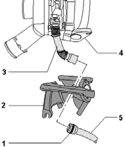
5.19. Return oil line connection details.
To avoid kinking these tubes, gently move the turbocharger back and forth while simultaneously pulling it up and to the side. After removing the turbocharger, position it so that it does not rest on the top of the oil return pipe.
20. If necessary, after removing the turbocharger, unscrew the bolts (see illustration) and remove the intermediate flange.
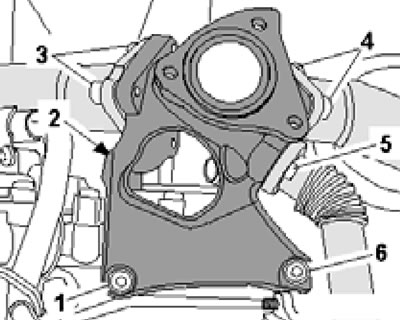
5.20. Fastening of intermediate flange.
21. Before installing the turbocharger, secure the hose to its connection (1 in the illustration) using two clamps (2).
5.21. Fastening the connecting hose.
Install a new O-ring (1 in illustration 5.19), onto the lower return fuel pipe, lightly lubricate it with engine oil and install the turbocharger, seating the upper pipe onto the lower one through the intermediate flange (2).
22. Further installation is carried out in reverse order. Use new sealing parts. Fill the turbocharger with oil through the oil supply line. After installation, let the engine idle for about a minute to ensure the compressor receives sufficient lubrication.
3.0L SCR engines (SATA, SSMA)
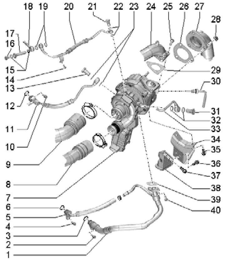
23. Turbocharger installation details are shown in the illustration.
5.23. Turbocharger installation details for SATA and CCMA engines:
1 - Tube to the switching valve of the additional EGR radiator, with a catalytic converter;
2, 9, 21, 24, 31, 34 - Gasket, subject to replacement;
3 - Intermediate flange;
4 - Bolt, 25 Nm;
5, 29 - Sealing ring, subject to replacement;
6, 8, 13, 17, 27, 30, 36 - Bolt, 9 Nm;
7 - Oil supply line from the cylinder block;
10 - Hollow bolt, 15 Nm;
11 - Right air tube;
12 - Air hose from turbocharger to tube 11;
14 - Connecting part of the air intake hose, from the MAF sensor to the turbocharger;
15 - Sensor No. 1 "G235" exhaust gas temperature;
16, 34 - Gasket;
18 - Turbocharger heat shield;
19 - Turbocharger with control unit No. 1 "J724";
20* - Bolt, to be replaced, 30 Nm, then tighten to an angle of 90°;
22 - Primary catalytic converter;
23 - Nut;
25* - Bolt, 7 Nm, then tighten to 9 Nm;
26 - Upper part of the return oil line, from the turbocharger;
28 - Lower part of the return oil line, to the cylinder block;
32 - Intermediate tube;
33 - Bolt;
35 - Bolt, 25 Nm.
Parts marked with "*" should be lubricated with high temperature grease before installation/tightening. Removing the compressor control unit requires a special electronic diagnostic tool, so this procedure is not described.
24. Remove the upper engine cover (see Section 19 of Chapter 1).
25. Remove the air hose (see illustration 15.6 Chapter 2).
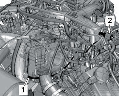
26. On models before 05.2010, remove the bolts (2 and 3 in the illustration), loosen the clamp (1) and separate the air hose from the right air tube.
5.26. Fastening and connecting the air tube.
27. On models from 06.2010, remove the bolts (2 and 3 in Illustration 5.14), loosen the clamp (1) and separate the air hose from the right air tube.
28. Remove the bolts (left arrows in illustration 5.11) connection and slide it to the side with the air intake hose connected (right arrow).
29. Disconnect the connector (2 in illustration 3.3 of Chapter 2) activator "V280" turbocharger. Remove the bolt (1) and the hollow bolt (3) of the oil supply line.
30. Remove the bolts (1 and 2 in Illustration 15.28 of Chapter 2) and remove the turbocharger heat shield.
31. Give the nuts (see illustration 4.61 Chapter 2) and remove the primary catalytic converter from the turbocharger.
32. Disconnect the black connector (1 in illustration 21.35 Chapter 2) sensor No. 1 "G235" exhaust gas temperature.
33. Remove the bolts (see illustration 5.18) turbocharger mounts.
34. Upper part of the return oil pipe (1 in illustration 5.19) is attached to the turbocharger and should be carefully separated from the lower part of the tube (5). To avoid kinking these tubes, gently move the turbocharger back and forth while simultaneously pulling it up and to the side. After removing the turbocharger, position it so that it does not rest on the top of the oil return pipe.
35. Before installing the turbocharger, install a new sealing ring (1 in illustration 5.19), onto the lower return fuel pipe, lightly lubricate it with engine oil and install the turbocharger, seating the upper pipe onto the lower one through the intermediate flange (2).
36. Further installation is carried out in reverse order. Use new sealing parts. Fill the turbocharger with oil through the oil supply line. After installation, let the engine idle for about a minute to ensure the compressor receives sufficient lubrication.
3.0L 2nd generation engines (CASA/CASB)
37. Turbocharger installation details are shown in the illustration.
5.37. Turbocharger installation details for 2nd generation 3.0L engines:
1, 15, 18, 21 - Gasket, subject to replacement;
2, 26 - Turbocharger bracket;
3 - Bolt, 23 Nm;
4 - Studs, after loosening the nuts, must be replaced, 10 Nm;
5 - Gasket;
6 - Turbocharger with control unit No. 1 "J724";
7 - Bracket for electrical wiring connector and upper engine cover;
8, 12 - Bolt, 9 Nm;
9 - Air hose connection, to the MAF sensor to the turbocharger;
10 - O-ring, must be replaced;
11 - PCV hose;
13, 19 - Nut*, subject to replacement;
14 - Sensor No. 1 "G235" exhaust gas temperature;
16 - Bolt, must be replaced;
17 - Tube to EGR radiator;
20 - Primary catalytic converter;
22* - Bolt, subject to replacement;
23 - Exhaust manifold;
24, 25 - Bolt.
Parts marked with "*" should be lubricated with high temperature grease before installation/tightening. Removing the compressor control unit requires a special electronic diagnostic tool, so this procedure is not described.
38. Remove the primary catalytic converter (see Part B).
39. Remove the air hose (see illustration 15.6 Chapter 2).
40. Loosen the clamp (1 in illustration 29.3 Chapter 2), unscrew the bolts (arrows) and remove the turbocharger pipe.
41. Remove the bolts (1 and 2 in the illustration).
5.41. Bolts.
42. Disconnect the PCV hose (see illustration 31.13 Chapter 2).
43. Disconnect the turbocharger connector (see illustration).
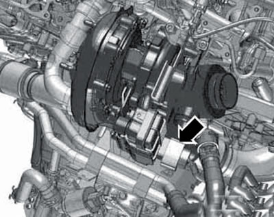
5.43. Turbocharger connector.
44. Remove the bolts (2 in the illustration), loosen the clamp (1) and disconnect the EGR pipe.
5.44. Removing the EGR pipe.
45. Remove the connector (2 in the illustration) from the bracket and disconnect. Move the wiring to the side.
5.45. Electrical wiring connector.
46. Remove the connector from the bracket (see illustration 25.16a in Chapter 2).
47. Loosen the bolt (5 in the illustration), loosen the nuts (1 and 2), unscrew the bolts (3 and 4) and remove the turbocharger.
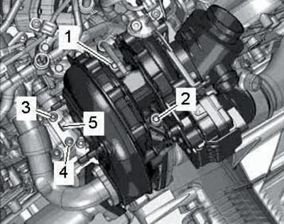
5.47. Turbocharger fastening.
48. Installation is carried out in reverse order. Use new sealing parts. Fill the turbocharger with oil through the oil supply line. Tighten the turbocharger fasteners in the following order: (see illustration 5.47): Tighten the studs for the nuts (1 and 2) with a force of 10 Nm, the nuts (1 and 2) by hand, then with a force of 9 Nm. Then tighten to an angle of 90°. Tighten the bolts (3-5) by hand, then the bolts (3 and 4) with a force of 9 Nm, then the bolt (5) with a force of 23 Nm.
49. After installation, let the engine idle for about a minute to ensure the compressor receives sufficient lubrication.
4.2L engines
50. The turbocharger installation details are shown in the illustration using the left turbocharger as an example.
5.50. Installation details of the left turbocharger of 4.2 L engines:
1, 5 - Return oil line;
2, 4, 40 - Bolt, 10 Nm;
3, 6, 12 - O-ring, subject to replacement;
7 - Turbocharger, on CCFA/CCFC engines - with speed sensor;
8 - Air pipe to the intercooler;
9 - Air tube from the air cleaner;
10 - Bolt, 22 Nm;
11, 33 - Coolant pipe;
13, 31 - Hollow bolt (on the left side, 25 Nm) or union nut (on the right side, 30 Nm);
14 - Bolt. 9 Nm;
15, 19, 22, 23, 26, 29, 32, 39 - Gaskets, subject to replacement;
16 - Threaded plug, 15 Nm;
17 - Hollow bolt, 25 Nm;
18 - Right oil supply line to the turbocharger;
20 - Left oil supply line to the turbocharger;
21 - Hollow bolt, 15 Nm;
24 - Exhaust manifold;
25* - Bolt, to be replaced, 20 Nm, then tighten to an angle of 90°;
27 - Primary catalytic converter;
28 - Nut;
30 - Sensor No. 1 "G236" exhaust gas temperature (left side) or sensor No. 1 "G235" exhaust gas temperature (right side);
34, 38 - Turbocharger bracket 35* Bolt, 40 Nm;
36, 37 - Bolt, 22 Nm.
Parts marked with "*" should be lubricated with high temperature grease before installation/tightening.
Left side
51. Remove the left catalytic converter (see Part B).
52. Disconnect the connector (3 in illustration 36.5 Chapter 2), unscrew the bolt (1), loosen the clamps (2 and 5) and remove the left air tubes.
53. Unscrew the bolt (1 in the illustration), loosen the clamp (arrow) and remove the air tube.
5.53. Bolt (1) and clamp (arrow) of the air tube.
54. Remove the bolts (2 and 3 in illustration 35.46 Chapter 2) and remove the turbocharger bracket.
55. Remove the bolts (1 in illustration 38.7 Chapter 2) fastening the oil and coolant supply lines to the turbocharger.
56. Remove the bolts (arrows in illustration 42.16 Chapter 2) fastening the turbocharger to the exhaust manifold.
57. On models with CCFA/CCFC engines, disconnect the connector (arrow in illustration 35.45 Chapter 2) and unscrew the bolt (3).
58. Disconnect the connector (arrow in the illustration) and remove sensor No. 1 "G236" (5).
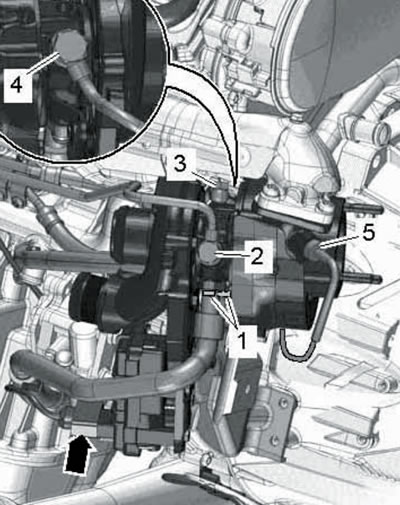
5.58. Connections and fasteners of the left turbocharger.
Remove the bolts (1) on the return oil line, remove the hollow bolt (2) of the coolant pipe and the hollow bolt (3) of the supply oil line. Tilt the turbocharger slightly to the left and remove the hollow bolt (4) securing the coolant pipe at the rear. Remove the turbocharger without applying force to the cast lever on its housing or the control unit. Plug the openings on the turbocharger and all associated air ducts and hoses in the boost system.
59. Installation is carried out in reverse order. Use new sealing parts. Fill the turbocharger with oil through the oil supply line. After installation, let the engine idle for about a minute to ensure the compressor receives sufficient lubrication.
Right side
60. Remove the right catalytic converter (see Part B).
61. Disconnect the connector (5 in illustration 35.49 Chapter 2), unscrew the bolt (1), loosen the clamps (2 and 3) and remove the right air pipes.
62. Unscrew the bolt (1 in illustration 35.50 Chapter 2). Loosen the clamp (arrow) and remove the right air pipe with the air hose for the turbocharger.
63. Unscrew the bolt (3 in illustration 38.10 Chapter 2) on the coolant pipe bracket.
64. Remove the bolts (2 in illustration 35.48 Chapter 2) from the turbocharger bracket.
65. Remove sensor No. 1 "G235" (1 in the illustration) and unscrew the bolts (arrows) securing the turbocharger to the exhaust manifold.
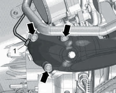
5.65. Sensor "G235" (1) and bolts (arrows) for fastening the turbocharger to the exhaust manifold.
66. Disconnect the connector (5 in the illustration) turbocharger control unit, and on CCFA/CCFC engines, additionally disconnect the connector (6) of the rotation sensor "G653".
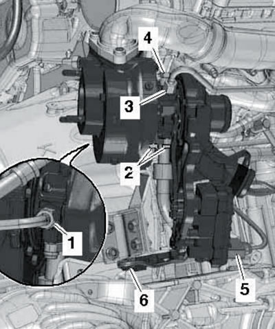
5.66. Connections and fasteners of the right turbocharger.
Unscrew the bolts (2) on the return oil line, loosen the union nut (3) of the coolant pipe and unscrew the hollow bolt (4) of the oil supply line. Tilt the turbocharger slightly to the right and loosen the union nut (1) on the coolant pipe at the rear. Remove the turbocharger without applying force to the cast lever on its housing or on the control unit. Plug the openings on the turbocharger and all associated air ducts and hoses in the boost system.
67. Installation is carried out in reverse order. Use new sealing parts. Fill the turbocharger with oil through the oil supply line. After installation, let the engine idle for about a minute to ensure the compressor receives sufficient lubrication.
(The original version of the article is posted on the website: «audimanual»)