
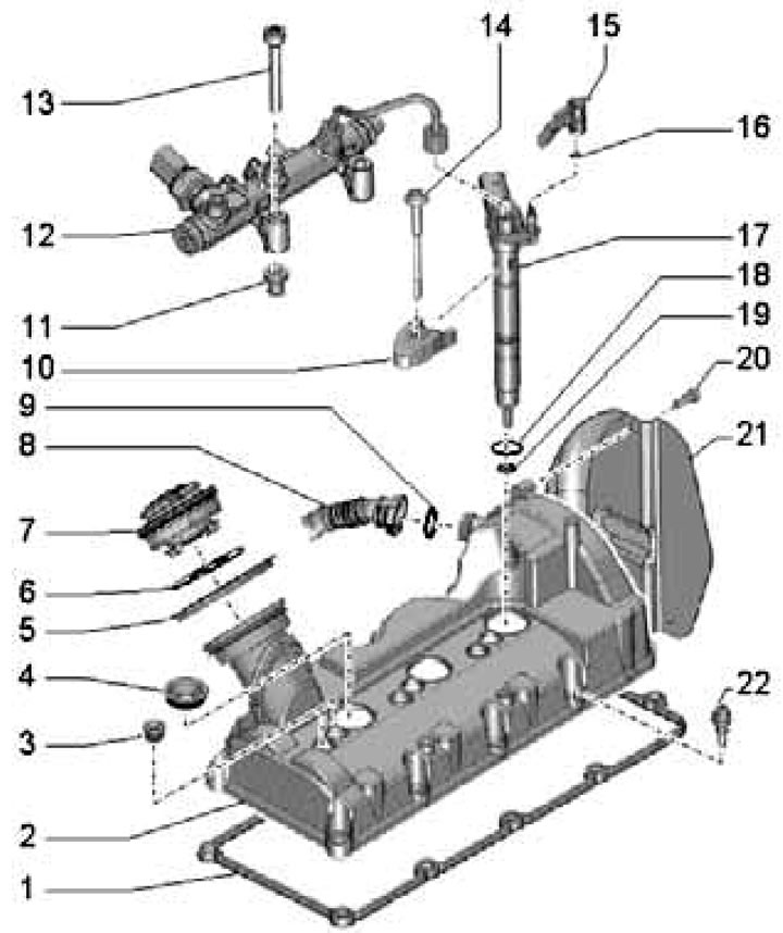
31.1a. Left cylinder head cover installation details:
1 - Cover gasket 2;
2 - Left cylinder head cover;
3 - Sealing plug;
4 - Injector seal;
5 - Gasket;
6 - Cover gasket 7;
7 - Oil filler cap;
8 - PCV hose;
9, 16, 18 - O-ring, subject to replacement;
10 - Nozzle holder;
11 - Mounting sleeve of the main line 12;
12 - Left fuel distribution line;
13 - Bolt, 22 Nm.
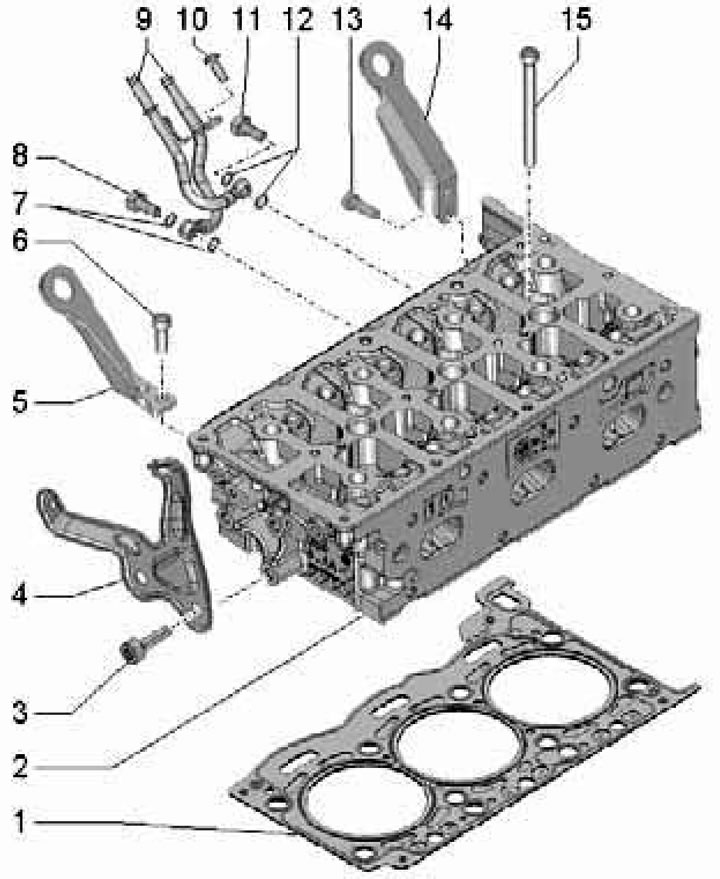
31.1b. Left cylinder head installation details:
1 - Cylinder head gasket, part number must face the cylinder head;
2 - Cylinder head;
3, 6, 13 - Bolt, 23 Nm;
4 - Bracket;
5, 14 - Lifting eye;
7, 12 - Sealing rings, subject to replacement;
8, 11 - Hollow bolt, 12 Nm;
9 - Coolant pipes;
10 - Bolt, 9 Nm;
15 - Bolt, must be replaced; tighten by hand, then to 35 Nm, then tighten to 60 Nm, and then tighten twice to a 90° angle.
Left cylinder head cover
2. Remove the top engine cover (see Section 19 of Chapter 1).
3. Remove the injectors and the fuel distribution line of the left cylinder head, as well as the activator "V157" of the intake manifold flap (see Chapter 4).
4. Remove the bolts (1 in the illustration) and remove the intake manifold bracket.
31.4. Bolts (1) for fastening the intake manifold bracket.
5. Remove the bolts (1 in illustration 29.2) and remove the heat shield (if available). Remove the wiring harness from the cylinder head cover.
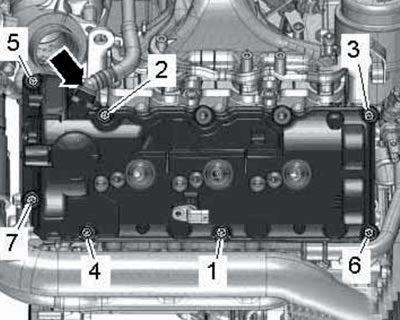
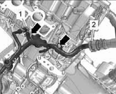
6. Move the vacuum hose aside and disconnect the PCV hose (arrows in the illustration), loosen the bolts in sequence (7-1), then completely unscrew them and remove the cylinder head cover.
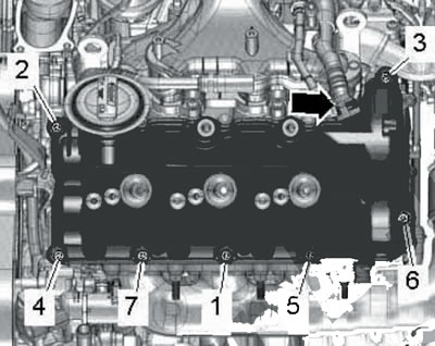
31.6. PCV hose (arrow) and fasteners (1-7) of the left cylinder head cover.
7. Clean the mating surfaces from oil and grease. Apply approximately 2mm wide beads of sealant to the joints between the cylinder head and the lower timing chain cover (see illustration).
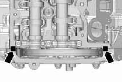
31.7. Places of sealant application.
8. Install the cylinder head cover and tighten its bolts in the sequence (1-7 in illustration 31.6) in three stages. First, tighten by hand, then with a torque of 8 Nm, and then tighten to a 90° angle. If the seals on the bolts are damaged, replace the bolts and seals.
9. Install the remaining removed parts.
Right cylinder head cover
10. Remove the top engine cover (see Section 19 of Chapter 1).
11. Remove the injectors and fuel rail from the right cylinder head (see Chapter 4).
12. Disconnect the connector (3 in the illustration) cMP sensor "G40" (2) and move the wiring away from the cylinder head cover.
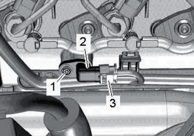
31.12. Connector (3) and bolt (1) of the CMP sensor (2).
13. Squeeze the clips and disconnect the PCV hose (see illustration).
31.13. PCV hose.
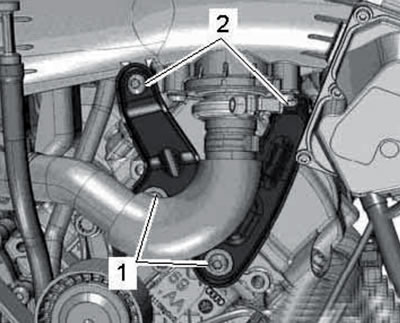
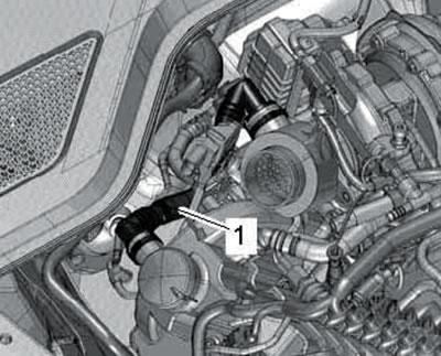
14. Remove the bolts (see illustration) and remove the turbocharger connection.
31.14. Turbocharger connecting bolts.
15. Disconnect the PCV hose (arrows in the illustration), loosen the bolts in sequence (7-1), then completely unscrew them and remove the cylinder head cover.
31.15. PCV hose (arrow) and fasteners (1-7) of the right cylinder head cover.
16. Clean the mating surfaces from oil and grease. Apply approximately 2mm wide beads of sealant to the joints between the cylinder head and the lower timing chain cover (by analogy with illustration 31.7).
17. Install the cylinder head cover and tighten its bolts in the sequence (1-7 in illustration 31.15) in three stages. First, tighten by hand, then with a torque of 8 Nm, and then tighten to a 90° angle. If the seals on the bolts are damaged, replace the bolts and seals.
18. Install the remaining removed parts.
Cylinder head
19. Drain the coolant (see Chapter 3).
20. Remove the turbocharger and intake manifold (see Chapter 4).
21. Remove the corresponding camshafts (see Section 32).
22. When working on the left cylinder head, perform the steps in paragraphs 23-25, then proceed to paragraph 30. When working on the right cylinder head, proceed to paragraph 26.
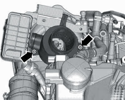
23. Loosen the clamps (1 and 2 in the illustration) and disconnect the coolant hoses.
31.23. Coolant hose clamps.
24. Remove the bolts (1 in the illustration) and disconnect the EGR pipe.
31.24. EGR pipe bolts (1).
25. Remove the union nut (left arrow in the illustration) and disconnect the high pressure fuel pipe (1).
31.25. Union nuts (arrows) of high pressure fuel pipe (1).
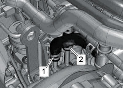
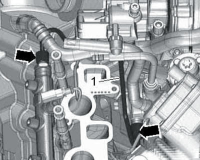
26. Remove the front coolant pipes (see Chapter 3), loosen the clamp (1 in the illustration), lift the retainer (2) and disconnect the coolant hoses.
31.26. Fastening and connections of coolant hoses.
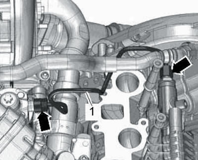
27. Unscrew the union nut (right arrow in the illustration) and disconnect the high pressure fuel pipe (1).
31.27. Union nuts (arrows) of high pressure fuel pipe (1).
28. Unscrew the hollow bolt (see illustration).
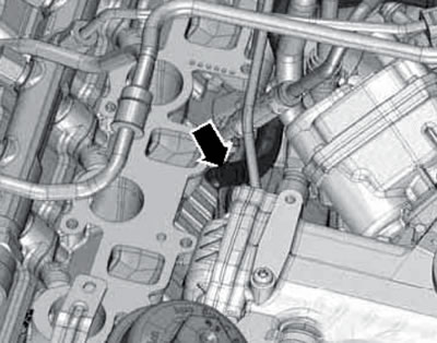
31.28. Hollow bolt.
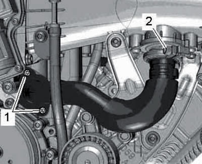
29. Unscrew the guide pins of the guide bar (1 in the illustration) and tensioner bars (2).
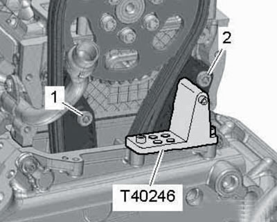
31.29. Guide pins (1 and 2) of the guide and tension strips.
30. Loosen the cylinder head mounting bolts in the sequence (1-8 in the illustration).
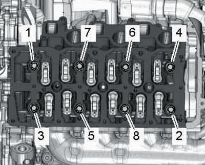
31.30. Sequence of unscrewing cylinder head bolts.
Then completely unscrew the bolts, carefully remove the cylinder head and place it on a soft surface, being careful not to damage the glow plugs.
31. Please take note of the comments listed in paragraph 20 of Section 11.
32. Make sure that the crankshaft is fixed at TDC with locking pin No. 3242 (see illustration 29.24), and the intake camshafts are locked at TDC using T40060 devices (see illustrations 29.27a-b).
33. Pay attention to the number of holes (2 in the illustration) and the part number (1) on the gasket.
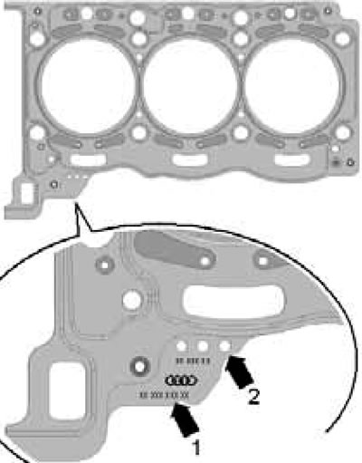
31.33. Identification of the cylinder head gasket.
The left and right cylinder head gaskets are different from each other. If the cylinder head or its gasket needs to be replaced, select a new gasket with the same number of holes as the old gasket. If the connecting rod and piston group parts have been replaced, it will be necessary to select a new gasket based on the piston protrusion at TDC (see Section 34).
34. Make sure that there are two centering bushings in the cylinder block, place a new cylinder head gasket on them, and then carefully place the cylinder head itself.
35. Tighten the new cylinder head bolts by hand. Tighten the cylinder head bolts in sequence (8-1 in illustration 31.30): with a force of 35 Nm, then with a force of 60 Nm, and then tighten twice to an angle of 90°.
Note: After this, tightening the bolts is not allowed.
36. Install the remaining parts in the reverse order of their removal.
The original article is available on the online resource audimanual.ru