
Table of contents: Removal and installation the old… ↓ Replacing camshafts and their… ↓ Checking hydraulic compensators ↓ Replacing valve stem seals ↓
Caution: After installing the camshafts, wait at least 30 minutes before starting the engine to allow the hydraulic lifters to settle. Otherwise, the valves may hit the pistons.
1. The installation details of the timing components are shown in the illustration using the example of the left cylinder head.
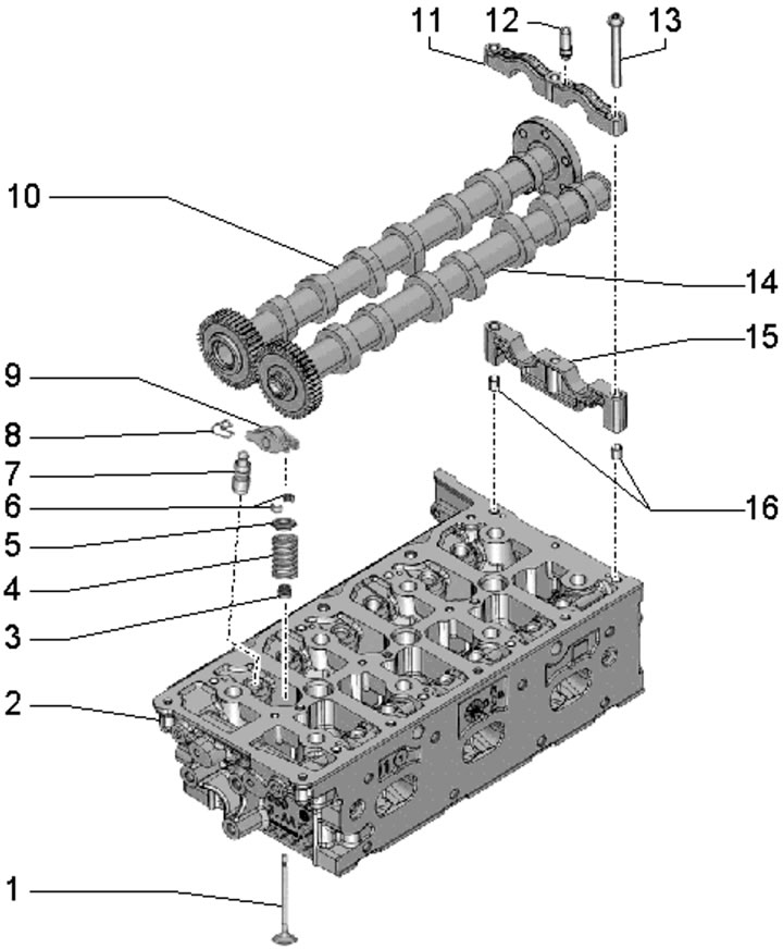
32.1. Timing belt component installation details (left cylinder head):
1 - Valve, sodium filled;
2 - Cylinder head;
3 - Oil deflector cap;
4 - Valve spring;
5 - Spring plate 4;
6 - Split valve lock crackers;
7 - Hydraulic valve clearance compensator, fixed in rocker arm 9;
8 - Retainer, not supplied separately;
9 - Rocker arm;
10 - Intake camshaft;
11 - Camshaft bearing cap;
12 - Nozzle holder support bracket;
13 - Bolt, 9 Nm;
14 - Exhaust camshaft;
15 - Camshaft bearing base;
16 - Spring pins, for rear base 15 with axle bearing only.
2. Processing of valves and their seats, except for lapping, is not permitted.
3. When working with the timing belt, arrange the removed parts so that they can then be installed in their original places.
Removal and installation the old camshafts
4. Remove the timing chain from the camshafts (see Section 29).
5. Make sure that the crankshaft is locked at TDC with locking pin No. 3242 (see illustration 29.24).
6. Make sure the camshafts are at TDC. It should be possible to lock the intake camshaft with the T40060 tool (see paragraph 9 of Section 9), and the groove (In the illustrations) in the exhaust shaft should be located parallel to the joint (A) of the bearing base/cap and slightly above it.
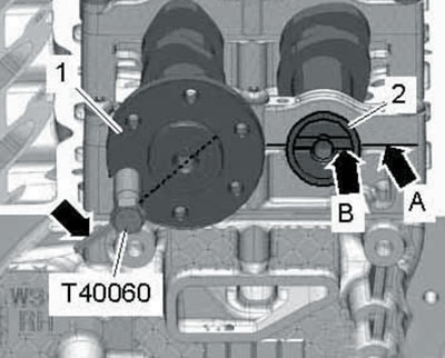
32.6a. Right cylinder head shafts at TDC.
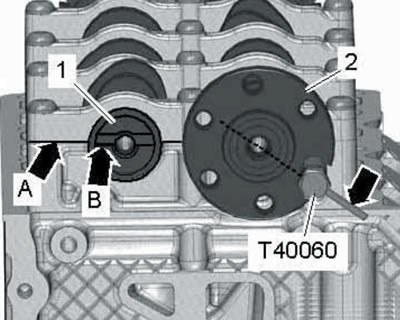
32.6b. Left cylinder head shafts at TDC.
7. Install the T40096 tool onto the intake shaft teeth so that the two arms of the tool engage the two halves of the gear (see illustrations).
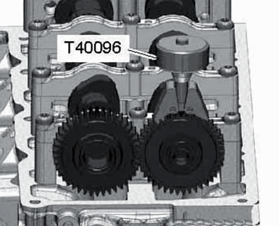
32.7a. Installing the T40096 tool on the right cylinder head.
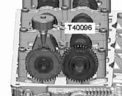
32.7b. Installing the T40096 tool on the left cylinder head.
The wider lever should fit on the wider half of the gear. Secure the fixture with a knurled nut so that the tooth surfaces align.
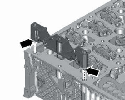
8. Install two plastic ties on each camshaft bearing (see illustration), so that the shafts and their bearings can be removed and then installed in their original position.
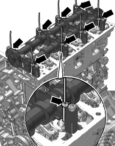
32.8. Preparation for removal of camshafts.
9. When working on the right cylinder head, remove the T40060 tool from the intake shaft and screw the two sprocket mounting bolts into the threaded holes by 5 turns, as shown in the illustration.
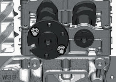
32.9. Bolts in threaded holes of the intake shaft (right head).
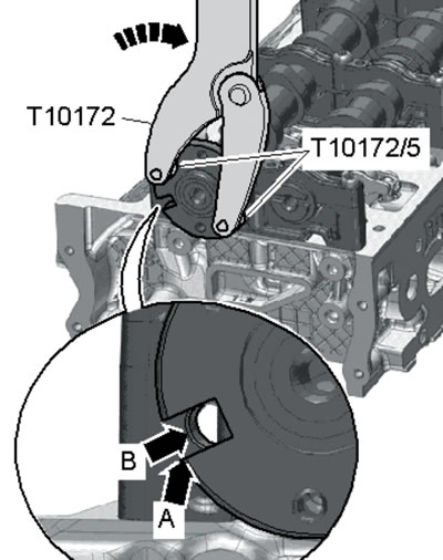
10. When working on the right cylinder head, install the T10172 tool with the T10172/5 adapters on the bolts and turn the shafts approximately 30° counterclockwise so that the groove (A) on the shaft flange is perpendicular to the lower plane of the cylinder head (B) and faces downwards.
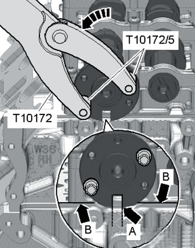
32.10. Turning the camshaft (right head).
Caution: Do not turn the shaft more than specified, otherwise the valves may be damaged.
11. Loosen the bearing bolts in sequence (12-1 in the illustrations) and carefully remove them together with the shafts.
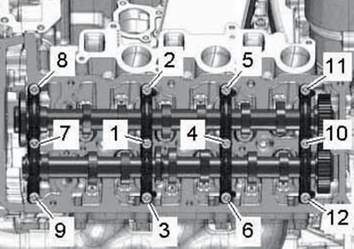
32.11a. Fastening of camshaft bearings of the right cylinder head.
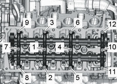
32.11b. Fastening of camshaft bearings of left cylinder head.
Note: If you intend to reinstall the removed shaft/bearings, do not loosen the clamps or swap the parts afterwards. If necessary, remove the rocker arms with hydraulic lifters.
12. Before installation, make sure that the crankshaft is fixed at TDC with locking pin No. 3242 (see illustration 29.24). and the T40096 device is installed on the intake shaft gear (see paragraph 7).
13. Install the camshafts together with their bearings, holding them by the clamps (see illustration 32.8). In this case, make sure that centering bushings are installed in the holes in the base of bearing No. 4 (see illustrations), which must fit into the holes in the cylinder head.
32.13a. Centering bushings (right head).
32.13b. Centering bushings (left head).
14. When working on the right cylinder head, follow the steps described in paragraphs 9-10.
15. Make sure the shafts are at TDC (see paragraph 6).
16. Tighten the camshaft bearing bolts in the sequence (1-12 in illustrations 32.11a-b) first by hand, and then with a force of 9 Nm.
17. When working on the right cylinder head, using the T10172 tool with the T10172/5 adapters, turn the shafts approximately 30° clockwise so that the groove (And in the illustration) on the shaft flange was located opposite the hole (B) for the T40060 device.
32.17. Returning shafts to TDC.
18. Check again that the shafts are at TDC (see paragraph 6). Remove the T40096 tool and install the timing chain (see Section 29).
Replacing camshafts and their bearings
19. Follow the steps in paragraphs 4-7 and 9-12.
20. Bearing bases and caps are marked on the release side (see illustrations): R - right head bearings, L - left head bearings, 1 - front bearing, 2 - front central, 3 - rear central, 4 - rear.
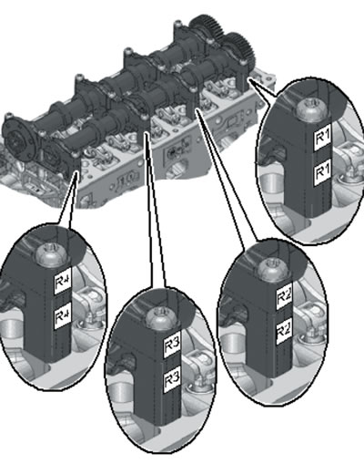
32.20a. Marking of bearings of shafts of the right cylinder head.
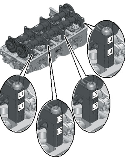
32.20b. Marking of bearings of shafts of left cylinder head.
The markings on the base and lid of a pair must be identical.
21. Install bearing bases No. 1-3 on the cylinder head so that the oil channels (1 in the illustration) in the cylinder head coincided with the oil channels (2) in the bearing bases.
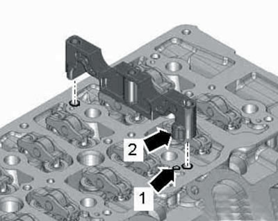
32.21. Installing bearing base No. 2.
22. Install bearing base No. 4 on the head so that the centering bushings installed in it enter the holes in the cylinder head (see illustration).
32.22. Installing bearing base No. 4.
23. Make sure that the bearing bases are installed correctly: round side (2 in the illustration) should face the inlet side and the rectangular side (1) should face the outlet side.
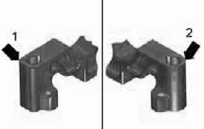
32.23. Correct orientation of the bearing base.
24. Make sure the shafts are at TDC(see paragraph), install the bearing caps on the corresponding bases and secure them with clamps (see illustration 32.8).
25. When working on the right cylinder head, follow the steps described in paragraphs 9-10.
26. Follow the steps described in paragraphs 16-18.
Checking hydraulic compensators
27. Checking the hydraulic compensators is carried out in the same way as on the 3.0 TDI engines of the 1st generation (see Section 12).
Replacing valve stem seals
28. To replace the valve stem seals, remove the camshafts and rocker arms with hydraulic compensators (see the relevant subsection above).
29. Set the piston of the corresponding cylinder to BDC and remove the glow plugs (see Chapter 5).
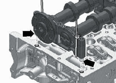
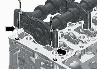
30. Use the tools shown in the illustration to compress the valve spring.
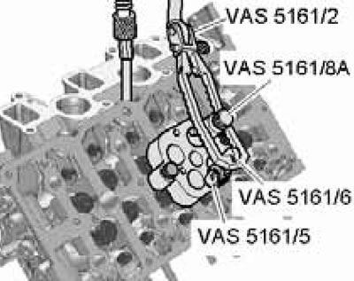
32.30. Devices for squeezing out valve springs.
To prevent the valve from falling into the cylinder, supply air to it through the spark plug hole under a pressure of at least 6 bar (if the work is performed without removing the cylinder head).
31. When installing the valve stem seals, use the plastic bushings included in the kit.